
Manual


3
wear, or physical damage. Check end-to-end electrical
continuity at terminals. NOTE: Potentiometer pin
locations will remain constant (see Figure 5). However,
cable assembly connector pin out may vary from engine
to engine.
2. Remove the ET-2
™
treadle from the vehicle.
3. Secure the ET-2
™
treadle to a smooth, flat surface in
such a way that it does not twist the unit.
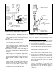
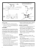
4. Connect the potentiometer to the volt meter and power
supply as shown in Figure 5. NOTE: Power supply
can be a 12 VDC vehicle battery in good condition and
with known voltage output.
5. Verify that the closed throttle (idle) output voltage, as
a percentage of supply voltage, is within the limits listed
in Figure 2.
6. Depress the treadle to its full throttle position. The
output voltage, as a percentage of supply voltage,
should be within the limits listed in Figure 2, e.g.
Testing a Detroit Diesel ET-2
™
Treadle Potentiometer:
Battery = 10 VDC. Full throttle = 9 VDC. 9/10 x 100 =
90%.
7. Make several full applications and record idle position
voltage each time. Verify that idle position voltage does
not vary by more than .4% (.02 volts). If the ET-2
™
treadle does not operate within its specified ranges,
service the unit, or replace it with a new ET-2
™
treadle,
available at your nearest Bendix parts outlet.
Test 2: For Cummins engines (featuring a separate
potentiometer and idle validation switch):
To test the potentiometer on the vehicle, use steps 1 through
8. Alternatively, instructions for carrying out a “bench test”
is covered in instructions 11 through 16.
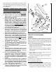
1. First construct the “breakout” harness shown in Figure 6.
2. Insert connector X on the breakout harness into the
connector leading from the potentiometer. Then insert
connector Y on the breakout harness into the connector
leading from the dashboard wire harness.
3. Next insert pin 1 into the ground position on a voltmeter.
Then insert pin 2 into the positive position on a volt
meter.
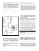
4. Disconnect the idle validation switch cable from the
dashboard wire harness. Connect an ohmmeter to pins
A and B on the connector leading from the idle
validation switch. The positive lead should be
connected to pin A and the negative lead should be
connected to pin B.
5. Turn the vehicle’s ignition key to the “battery on”
position. This supplies a 5 volt input to the
potentiometer. Since the idle validation switch is no
longer connected, a fault code may be triggered on
some vehicles. This fault code will be reset at the end
of this test.
FIGURE 6 - ET-2
™
TREADLE ELECTRICAL TEST
SCHEMATIC FOR THE CUMMINS CONNECTOR
PACKARD ELECTRIC
CONNECTOR 12015793
(CONNECTOR Y)
C B A
PACKARD ELECTRIC
CONNECTOR 12010717
(CONNECTOR X)
A B C
GROUND PIN 1
OUTPUT PIN 2
INPUT PIN 3
FIGURE 5 - ET-2
™
TREADLE ELECTRICAL TEST
SCHEMATIC FOR THE DETROIT DIESEL CONNECTOR
POTENTIOMETER
PC. NO. ON THIS
SURFACE
POWER
SUPPLY
(9-16 VDC)
RESISTOR
TEST LOAD
(47,000 OHM FOR
DETROIT DIESEL,
300,000 OHM
FOR MACK)
DIGITAL
VOLT/
OHM
METER
PIN C
GROUND
PIN B
VOUT
(OUTPUT)
PIN A
VREF
(INPUT)
POTENTIOMETER