
Manual


4
6. Record the output voltage when the pedal is in the idle
position (V1). Then slowly depress the pedal. When
the ohm meter shows that the resistance has changed
from “overload” to about .003 ohms (or from .003 ohms
to “overload”), stop depressing the pedal. Record the
voltage (Vx) registered with the pedal in this position.
Then press the pedal to the full throttle position and
record the output voltage (V2).
7. Calculate the “switch point percentage” using the formula
below.
Switch point percentage = ((Vx-V1)/(V2-V1))*100
Vx = Output voltage when the switch changed
V1 = idle voltage
V2 = full throttle voltage
The following instructions are for a bench test for the
potentiometer used with Cummins engines.
10. Unplug the cable assembly from the potentiometer’s
integral connector by lifting the lock tab and pulling the
connectors until they disengage. Inspect cable
assembly for loose terminals, frayed wires, corrosion,
wear, or physical damage. Check end-to-end electrical
continuity at terminals. NOTE: Potentiometer pin
locations will remain constant (see Figure 5). However,
cable assembly connector pin out may vary from engine
to engine.
11. Remove the ET-2
™
treadle from the vehicle.
12. Secure the ET-2
™
treadle to a smooth, flat surface in
such a way that it does not twist the unit.
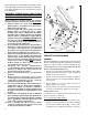
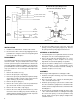
13. Connect the potentiometer to the volt meter and power
supply as shown in Figure 5. NOTE: Power supply
can be a 12 VDC vehicle battery in good condition and
with known voltage output.
14. Verify that the closed throttle (idle) output voltage, as a
percentage of supply voltage, is within the limits listed
in Figure 2.
15. Depress the treadle to its full throttle position. The
output voltage, as a percentage of supply voltage, should
be within the limits listed in Figure 2. e.g. Testing a
Detroit Diesel ET-2
™
Treadle Potentiometer: Battery =
10 VDC. Full throttle = 9 VDC. 9/10 x 100 = 90%.
16. Make several full applications and record idle position
voltage each time. Verify that idle position voltage does
not vary by more than .4% (.02 volts). If the ET-2
™
treadle does not operate within its specified ranges,
service the unit, or replace it with a new ET-2
™
treadle,
available at your nearest Bendix parts outlet.
Test 3: For Cummins engines (with integrated switch
and sensor (ISS): For use only with the Cummins Celet
Plus and later editions of the ECU. This sensor can
not be used to replace the separate potentiometer &
idle validation switch. To do this a new ET-2
™
treadle
with the ISS must be purchased.
Test 1: Where the set resistance and voltage is shown
on a label. The Cummins potentiometer on the ET-2
™
treadle has an integral idle validation switch. It also has a
set resistance value marked on the cover, which needs to
be used to properly install the potentiometer. The drive
slot in the potentiometer should engage with the drive
tang at the end of the drive shaft. Next rotate the
potentiometer until the hole in the metal sleeve matches
the mounting holes on the actuator base. Loosely screw
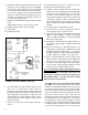
the potentiometer in place but do not tighten. Connect
an ohmmeter to pins 3 (APS output) and 4 (APS ground)
as shown in Figure 8. Now the installer should read the
set resistance value marked on the label. Rotate the
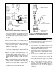
POTENTIOMETER
PC. NO. ON THIS
SURFACE
POWER
SUPPLY
(9-16 VDC)
RESISTOR
TEST LOAD
47,000 OHM
DIGITAL
VOLT/
OHM
METER
PIN C
GROUND
PIN B
VOUT
(OUTPUT)
PIN A
VREF
(INPUT)
POTENTIOMETER
8. The switch point percentage should be between 3% to
10%. If it is not with in this range adjust the
potentiometer by loosening the mounting screws and
turning the potentiometer within the range allowed by
the mounting holes. Repeat steps 1-7 again. If you can
not obtain the proper switch point percentage, replace
with a new ET-2
™
treadle, available at your nearest
Bendix parts outlet.
9. After a successful test the vehicle may be returned to
service.
FIGURE 7 - ET-2
™
TREADLE ELECTRICAL TEST
SCHEMATIC FOR THE CUMMINS CONNECTOR