
Manual


6
INSTALLATION
1. Install the assembled ET-2
™
treadle on the vehicle.
2. Reconnect the cable connector by plugging it into the
potentiometer’s integral connector and pushing until
the lock tab snaps into place.
DISASSEMBLY
The following instructions present a major disassembly of
the ET-2
™
treadle. They are included for reference only.
Several replacement parts and maintenance kits that do
not require full disassembly are available. The instructions
provided with those items should be followed in lieu of the
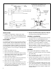
steps presented here. Refer to Figure 4 throughout the
procedures.
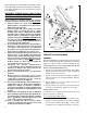
1. Remove the treadle cover (1).
2. Remove the pivot pin’s snap ring (8).
3. Remove the pivot pin (9) and the two nyliner bearings
(10) from the treadle’s exterior. Also remove the two
nyliner bearings (10) from the mounting base.
4. Remove the pivot spring (11).
5. Remove the screws (3) that secure the potentiometer
(2) to the treadle. Remove the potentiometer.
6. Remove the lever shaft’s snap ring (5).
7. Remove the lever shaft (4) and the washer (7). Then
remove the roller assembly (15), the inner washer (5),
and the nyliner bearing (6) from the treadle. Separate
the treadle from the mounting base.
8. The roller assembly consists of the lever, roller, two
springs (12 & 13), and a spring support (14). Remove
the springs and the spring support from the lever.
CLEANING & INSPECTION
1. Use mineral spirits or an equivalent solvent to clean all
metal parts. Be sure to thoroughly dry the parts.
2. Inspect the treadle and mounting base for severe
corrosion, pitting, or cracks. Replace as necessary.
Superficial corrosion and/or pitting is acceptable.
3. Inspect the cable assembly for loose or frayed wires,
physical damage, or any contaminants on the
connectors. Check end-tend electrical continuity at
terminals. Replace as necessary.
ASSEMBLY
Refer to Figure 4 throughout the assembly procedure.
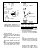
1. Install the four nyliner bearings (10) on the mounting
base and treadle.
2. Place the treadle “ears” outside the mounting base
“ears” so that the holes line up.
3. Install the pivot spring (11) into the base and treadle.
The curved end of the spring fits into a small hole in the
treadle, and the straight end fits into a small hole in the
mounting base.
4. The pivot pin (9) should slide through the holes in the
“ears” of the treadle and base assembly, then through
the center of the spring. Secure the pin with its snap
ring (8). Make sure the pivot spring is straight and is
seated in its holes.
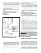
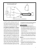
FIGURE 8 - ET-2
™
TREADLE ELECTRICAL TEST SCHEMATIC FOR THE CUMMINS CONNECTOR
.01µF
TEST LOAD
47000 OHM
IDLE
VALIDATION
SWITCH
IVS
PEDAL
POSITION
SENSOR
PIN 3
PIN 4
PIN 5
Vs
SUPPLY
VOLTAGE
V1
(OUTPUT)
APS
GROUND
PIN 2
PIN 6
PIN 1
TEST
LOAD
470
OHM
TEST
LOAD
470
OHM
Vs
SUPPLY
VOLTAGE
DIODES
Closed Throttle (open) Range: 5-17%
Open Throttle (full) Range: 70-81%
V3 (LOGIC HIGH AT IDLE)
V2 (LOGIC LOW AT IDLE)
IVS GROUND
3
V1
(OUTPUT) SIG1
2
(IVS) V 2
1
IVS GROUND
6
(IVS)
V 3
5
VS
(INPUT)
4
APS GROUND
POTENTIOMETER
SET VOLTAGE
AND PC. NO.
SHOWN
HERE
LOCK TAB
LOCK TAB