
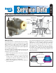
QUICK RELEASE VALVE User Manual

2
OPERATION
SPRING BRAKES RELEASED
When the spring brakes are released, air from the park
control valve fl ows through the QR-1C
®
valve, causing
the double check valve and quick release diaphragms to
fl ex and seal the balance and exhaust ports. Air fl ows into
the emergency port of the spring brakes from the QR-1C
®
valve delivery ports.
SPRING BRAKES APPLIED
When the spring brakes are applied, supply line air pressure
to the valve is exhausted through the park control valve.
As air pressure is removed from one side of the double
check valve and quick release diaphragms, they fl ex in
the opposite direction opening the balance and exhaust
ports. Spring brake emergency pressure is released at
the exhaust port of the valve while the small amount of air
trapped between the two diaphragms is released through
the relay valve or brake valve exhaust.
ANTI-COMPOUNDING
When a service brake application is made with the spring
brakes applied, service air enters the balance port and
fl ows through the valve into the emergency ports of the
spring brakes. This prevents the compounding of a service
and spring brake application. Service air passing through
the valve flexes the double check and quick release
diaphragms, sealing the supply and exhaust ports. When
the service application is released, air is exhausted from
the spring brakes.
PREVENTIVE MAINTENANCE
Important: Review the Bendix Warranty Policy before
performing any intrusive maintenance procedures. A
warranty may be voided if intrusive maintenance is
performed during the warranty period.
No two vehicles operate under identical conditions, as
a result, maintenance intervals may vary. Experience is
a valuable guide in determining the best maintenance
interval for air brake system components. At a minimum, the
QR-1C
®
valve should be inspected every 12 months or
3600 operating hours, whichever comes fi rst, for proper
operation. Should the QR-1C
®
valve not meet the elements
of the operational tests noted in this document, further
investigation and service of the valve may be required.
REMOVAL
1. Block vehicle wheels and/or hold vehicle by means
other than air brakes.
2. Drain all air brake system reservoirs.
3. Identify and disconnect air lines from valve.
4. Remove mounting bolts, then valve.
DISASSEMBLY
Mark the relationship of the body and cover before
disassembly.
1. Remove cap nut.
2. Remove sealing ring from cap nut.
3. Remove double check valve diaphragm.
4. Remove four Phillips head screws.
5. Separate the body and cover and remove the sealing
ring and quick release diaphragm.
CLEANING AND INSPECTION
Clean all metal parts in mineral spirits. Wipe all rubber
parts clean. It is recommended that all rubber parts and
any other part showing signs of wear or deterioration be
replaced with genuine Bendix
®
parts.
ASSEMBLY
1. Install sealing ring on cap nut.
2. Install double check valve diaphragm in body.
3. Install cap nut and torque to 150-400 inch pounds.
4. Install sealing ring in valve body.
5. Install the quick release diaphragm in the cover.
6. Install the cover and diaphragm on body, aligning the
marks made during disassembly. Secure together using
the four Phillips head screws and torque to 30-60 inch
pounds.
7. Re-install the QR-1C
®
valve and before putting the
vehicle in service, perform the “Operation and Leakage
Tests.”
OPERATING AND LEAKAGE TESTS
Before performing these tests, park the vehicle on a level
surface and hold the vehicle by means other than the
brakes.
1. With the park control valve in the released position,
note that the spring brakes are released.
2. Remove the air line connected to the QR-1C
®
valve
balance port and apply a soap solution to the exhaust
and balance port. A 1" bubble in 5 seconds is permissible
at either location.
3. Reconnect the QR-1C
®
valve balance line; and using
the park control valve, park the vehicle. NOTE: A prompt
application of the spring brakes with an exhaust of air
at the QR-1C
®
valve exhaust port.
4. Remove the air line connected to the supply port of the
QR-1C
®
valve. With a service brake application hold
applied, apply a soap solution to the supply port and
around the seam between the body and cover. A 1"
bubble in 5 seconds is permissible at the supply port.
No leakage is permitted between the body and cover.