
User Manual


5
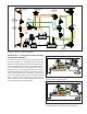
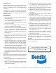
OPERATION - PARKING (FIGURE 7)
When the handle of the parking control valve is placed
in the “park” (exhaust) position, the modulating valve’s
supply air pressure, along with the air pressure in the
spring brake actuator cavities is exhausted. The single
check valve speeds the exhaust of air from the actuator
cavities by allowing the air on top of the balance piston
to exhaust by the double check valve through the supply
port to atmosphere. When air pressure drops sufciently,
the balance piston opens the inlet valve, thus opening the
larger passage in the modulating valve. This ensures rapid
exhaust of the balance of air pressure in the spring cavity
of the spring brake actuator.
PREVENTIVE MAINTENANCE
IMPORTANT
Review the Bendix Warranty Policy before performing
any intrusive maintenance procedures. A warranty may
be voided if intrusive maintenance is performed during
the warranty period.
No two vehicles operate under identical conditions, and that
means, maintenance intervals may also vary. Experience
is a valuable guide in determining the best maintenance
interval for air brake system components. At a minimum,
the Bendix
®
R‑7
™
modulating valve should be inspected
every six (6) months or 1500 operating hours, whichever
comes rst, for proper operation. Should the R-7 valve not
meet the elements of the operational tests noted in this
document, further investigation and service of the valve
may be required.
OPERATING TEST
Block the vehicle and hold it by means other than the
vehicle brakes. Charge the air brake system to governor
cut‑out pressure.
1. Place the parking control valve in “park” position.
Observe that the spring brake actuators apply promptly.
Remove the air line from the delivery port of valve and
install a test gauge known to be accurate. Place the
parking control valve in the “release” position. Observe
that the spring brake actuators release fully.
2. With the parking control valve in the “release” position,
note the gauge pressure reading. (Check the vehicle
manual for correct spring brake actuator hold‑off
pressure.)
3. Place the parking control valve in the “park” position—
the gauge reading should drop to zero promptly. A
lag—more than one (1) second—in drop of pressure
would indicate faulty operation of the single check valve
(within the modulating valve).
4. With the parking control valve in the “park” position,
fully apply the foot brake valve several times and note
a pressure reading increase on the gauge each time
the brake is applied. If the pressure reading does not
occur, the modulating valve must be either serviced or
replaced.
5. Place the parking control valve in the “release” position.
Identify the reservoir which supplies the balance port
and drain it completely.
Apply the foot brake valve several times and note that the
pressure reading on the gauge decreases each time the
foot brake valve is applied. After the foot brake valve has
been applied several times, pressure on the gauge will drop
to the point where the release of the spring brake actuators
will no longer occur.
FIGURE 7 - PARKING
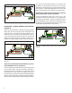
FIGURE 8 - ANTI‑COMPOUNDING WHILE PARKING