
Manual


4
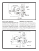
FIGURE 6 - PARK RELEASE WITH TRAILER CHARGED
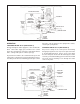
FIGURE 5 - PARK APPLICATION
TRAILER SUPPLY
SPRING
BRAKE
CHAMBER
TRAILER SERVICE RES.
CONTROL PISTON
EXHAUST
PASSAGE
TRAILER SERVICE
CHECK
VALVE B
SERVICE/
SPRING
BRAKE
RESERVOIR
CONNECTION
SERVICE
RELAY
VALVE
PRESSURE
PROTECTION
VALVE C
SPRING
BRAKE
CHAMBER
TRAILER SERVICE RES.
EXHAUST
PASSAGE A
TRAILER SERVICE
CHECK
VALVE B
SERVICE/
SPRING BRAKE
RESERVOIR
CONNECTION
SERVICE
RELAY
VALVE
CHECK
VALVE D
CONTROL PISTON
TRAILER SUPPLY
CHECK
VALVE F
CHECK
VALVE D
PARK APPLICATION (SEE FIGURE 5)
To park the trailer, either the trailer air supply valve or the
system park control valve (in the tractor) is actuated. This
vents the trailer supply line. The control piston, no longer
under supply pressure, is moved by air pressure on its
delivery side. This allows the control piston to move to the
exhaust position. The control inlet valve closes and the
exhaust valve opens, allowing air from the spring brakes
to exhaust through the passage in the control piston and
apply the brakes. Check valves B and D close, preventing
trailer reservoir air pressure loss through passage A.
PARK RELEASE WITH TRAILER CHARGED
(SEE FIGURE 6)
To release a park application with the trailer charged, the
trailer supply valve (in the cab) is actuated. Air fl ows through
the trailer supply line and enters the Bendix
®
SR-5
™
valve
trailer supply port. With a minimum of 55 psi on the control
piston, the piston will move, sealing its exhaust passage.
As piston travel continues, the inlet valve opens. Reservoir
air (approx. 110 psi) then fl ows through check valve F, past
the open inlet, and out to the spring brake chambers to
release the brakes.