
Manual

9
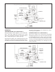
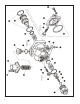
1. Remove the four screws (1) that secure the spring
retainer (2) to the valve body. Note that the retainer is
spring-loaded. Remove the screws while holding the
retainer against its spring load. Then slowly remove the
retainer.
2. Remove spring (3) and piston assembly (4).
3. Remove piston o-ring (5). Do not remove the retaining
ring and stem from the piston. The piston is serviced
as an assembly.
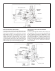
4. Note and mark the position of control piston cover (7).
Then remove the four screws (6) that secure the cover
to the body.
5. Remove cover (7) and sealing ring (8), control piston
(9), and spring (10).
6. Remove o-rings (11 & 12) from piston assembly.
7. Remove reservoir fi tting (13) and o-ring (14).
8. Remove spring (15) and inlet/exhaust valve (16).
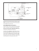
9. Remove the pipe plugs that retain the three single check
valves. Two check valves are in the body, and one is
in the cover (7).
10. Remove check valve springs (17) and rubber check
valves (18).
11. With a pair of I.D. snap ring pliers, remove the snap
ring (19) in the end of the reservoir fi tting check valve
assembly. Remove spring seat (20), spring (21), and
check valve (22).
12. Remove screw (23), washer (24), and diaphragm (25)
from the exhaust port.
CLEANING AND INSPECTION
1. Inspect all parts for excessive wear or deterioration.
Inspect valve seats for nicks or burrs. Check the springs
for cracks or corrosion.
2. Inspect the bores of the valve housing for deep scuffi ng
or gouges.
Replace all non-metallic parts and any part not found to be
serviceable during inspection, using only genuine Bendix
replacement parts.
ASSEMBLY
Before assembling the Bendix
®
SR-5
™
valve, lubricate all
o-rings, o-ring grooves, piston bores, and metal-to-metal
moving surfaces with Bendix silicone lubricant BW-650-M
piece number 291126.
NOTE: When using pipe thread sealant during assembly
and installation, take particular care to not allow
the sealant to get into the valve itself. Apply the
sealant beginning with the second thread back
from the end.
1. Twist the springs (17) on each of the check valves (18).
Drop the assemblies into their respective bores in the
valve body and install the pipe plugs. Torque the plugs
to 140-170 inch pounds.
2. Place reservoir fi tting (13) upright, pipe threads down.
Drop check valve (22) into place. Install check valve
spring (21), spring seat (20), and snap ring (19). Install
o-ring (14) into fi tting.
3. Install inlet/exhaust valve (16) into valve body. NOTE:
The side with four protruding ears rests against the seat
in the body.
4. Place spring (15) in position on the inlet/exhaust valve.
Make sure the spring rests evenly on the four ears of
the inlet/exhaust valve and the rubber protrusion on
the valve fi ts into the spring’s inner diameter.
5. Properly align the inlet/exhaust valve springboard in
the recess at the end of the reservoir port fi tting (13).
Install the fi tting into the valve body. Torque to 200-300
inch pounds.
6. Install o-rings (11 & 12) into their respective grooves in
the control piston (9).
7. Drop and position the spring (10) into the valve body.
8. Make sure all parts are properly aligned, and install the
control piston (9) into the valve body.
9. Install sealing ring (8) in the cover (7), and install
cover onto valve body, using the identifi cation made
in DISASSEMBLY step 4. Torque screws (6) to 40-60
inch pounds.
10. Install o-ring (5) in its groove in the pressure protection
piston (4). Install the piston assembly into the valve
body.
11. Position the spring (3) and spring retainer (2) on top of
the pressure protection piston assembly, and secure it
with the four screws (1). Torque to 20-30 inch pounds.
12. Install diaphragm (25), washer (24) and screw (23) into
the exhaust port. Torque screw to 15-25 inch pounds.
NOTE: BEFORE PLACING THE VEHICLE BACK INTO
SERVICE, PERFORM “OPERATIONAL AND
LEAKAGE TESTS,” LISTED IN THIS MANUAL.
BW1680 © 2011 Bendix Commercial Vehicle Systems LLC. All rights reserved. 4/2011 Printed in U.S.A.