
Owner's manual

2
DESCRIPTION
The Bendix
®
SV-1
™
synchro valve and the Bendix
®
SV-3
™
trailer release valves are pilot operated, non-graduating
pneumatic control valves. These valves are used to control
air from a remote supply, have set opening and closing
pressures and can be used to delay or sequence the action
of other pneumatic devices.
GENERAL
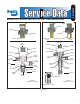
The SV-1 synchro valve (! gure 1) and SV-3 & Bendix
®
SV-4
™
trailer release valves (! gure 2) are air controlled,
“on-off” (non-graduating) control valves that are primarily
used to delay or sequence various devices and events
in the air brake system. These valves can be operated
either in an automatic or manual mode using different air
connection methods.
Two .28 inch diameter mounting holes are provided in the
die cast aluminum body for panel — or frame — mounting.
Two hex cap nuts at the ends of the cylindrical valve body
retain the internal components. The air connection ports
for the SV-1, SV-3 & SV-4 valves are the same — and are
located in relatively the same position — on each model.
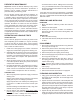
All connections are pipe thread. Lettering embossed in the
valve body identi! es two of the four connection ports in
these valves. Refer to the chart below and Figures 1 & 2.
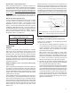
IMPORTANT: An exhaust check valve should be installed
in the threaded exhaust port of these valves when they
are mounted outside the cab in unprotected environments.
SV-1 Synchro Valve
The SV-1 valve is a general purpose valve used in a
variety of applications on trucks, buses, tractors, trailers
and converter dollies. The SV-1 valve is the base valve
from which both the SV-3 and SV-4 valves are derived. It
is offered in a variety of pressure settings to accommodate
applications where automatic operation is required. It is
easily distinguished from the SV-3 and SV-4 valve by its
smaller size.
FIGURE 3 - EXHAUST CHECK VALVE
1/8" PIPE THREAD
Exhaust Check Valve for Bendix
®
SV-1
™
, SV-3
™
and SV-4
™
valves.
Air
Connection Port I.D. Thread Size
Supply SUP 1/4" PT
Delivery DEL 1/4" PT
Control None 1/4" PT
Exhaust None 1/8" PT
GENERAL SAFETY GUIDELINES
WARNING! PLEASE READ AND
FOLLOW THESE INSTRUCTIONS
TO AVOID PERSONAL INJURY OR DEATH:
When working on or around a vehicle, the following
guidelines should be observed AT ALL TIMES:
▲ Park the vehicle on a level surface, apply the parking
brakes and always block the wheels. Always wear
personal protection equipment.
▲ Stop the engine and remove the ignition key when
working under or around the vehicle. When working
in the engine compartment, the engine should be shut
off and the ignition key should be removed. Where
circumstances require that the engine be in operation,
EXTREME CAUTION should be used to prevent personal
injury resulting from contact with moving, rotating,
leaking, heated or electrically-charged components.
▲ Do not attempt to install, remove, disassemble or
assemble a component until you have read, and
thoroughly understand, the recommended procedures.
Use only the proper tools and observe all precautions
pertaining to use of those tools.
▲ If the work is being performed on the vehicle’s air brake
system, or any auxiliary pressurized air systems, make
certain to drain the air pressure from all reservoirs
before beginning ANY work on the vehicle. If the vehicle
is equipped with a Bendix
®
AD-IS
®
air dryer system, a
Bendix
®
DRM
™
dryer reservoir module, or a Bendix
®
AD-9si
™
air dryer, be sure to drain the purge reservoir.
▲
Following the vehicle manufacturer’s recommended
procedures, deactivate the electrical system in a manner
that safely removes all electrical power from the vehicle
.
▲ Never exceed manufacturer’s recommended pressures.
▲ Never connect or disconnect a hose or line containing
pressure; it may whip. Never remove a component or
plug unless you are certain all system pressure has
been depleted.
▲ Use only genuine Bendix
®
brand replacement parts,
components and kits. Replacement hardware, tubing,
hose, fi ttings, etc. must be of equivalent size, type
and strength as original equipment and be designed
specifi cally for such applications and systems.
▲ Components with stripped threads or damaged parts
should be replaced rather than repaired. Do not
attempt repairs requiring machining or welding unless
specifi cally stated and approved by the vehicle and
component manufacturer.
▲ Prior to returning the vehicle to service, make certain all
components and systems are restored to their proper
operating condition.
▲ For vehicles with Automatic Traction Control (ATC),
the ATC function must be disabled (ATC indicator
lamp should be ON) prior to performing any vehicle
maintenance where one or more wheels on a drive axle
are lifted off the ground and moving.
▲ The power MUST be temporarily disconnected
from the radar sensor whenever any tests USING A
DYNAMOMETER are conducted on a Bendix
®
Wingman
®
Advanced
™
-equipped vehicle.
▲ You should consult the vehicle manufacturer's
operating and service manuals, and any related
literature, in conjunction with the Guidelines above.