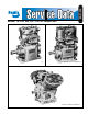
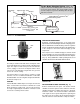
SD-01-326 ® Bendix® TU-FLO® 400, 500, 1000 Air Compressors TU-FLO® 400 Air Compressor TU-FLO® 500 Air Compressor TU-FLO® 1000 Air Compressor 1
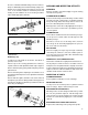
DESCRIPTION AND OPERATION GENERAL The function of the air compressor is to build up and maintain the air pressure required to operate air powered devices in air brake or air auxiliary systems. and they have no external moving parts. Both air and water cooled type compressors are available. Various mounting and drive adaptations are used as required by different vehicle engine designs (Fig. 4). DESCRIPTION Tu-Flo® Type 400, 500, and 1000 compressors are single stage, reciprocating piston type compressors.
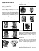
OPERATION GENERAL FIGURE 5 ENGINE LUBRICATED TYPE FIGURE 6 SELF-LUBRICATED TYPE had either die cast aluminum, cast ductile iron, or forged steel rods which were not rifle drilled but were drilled at the top of the rod. The wrist pins and bushings are lubricated by oil dripping from a drip-boss on the piston into a “catch-funnel” at the top of the rod and through the drilled passage to the bushings and pins. (SEE FIG.
As the piston reaches the top of its stroke and starts down, the discharge valve spring returns the discharge valve to its seat. This prevents the compressed air in the discharge line from returning to the cylinder bore as the intake and compression cycle is repeated.
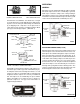
The Air Brake Charging System supplies the Discharge Line Optional “Ping” Tank Air Dryer compressed air for the braking system as well as other air accessories for the vehicle. The system usually consists of an air compressor, governor, discharge line, air dryer, and service reservoir.
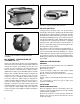
FIGURE 16 - COMPRESSOR INTAKE ADAPTER FIGURE 14 - POLYURETHANE SPONGE STRAINER AIR LEAKAGE TESTS Leakage past the discharge valves can be detected by removing the discharge line, applying shop air back through the discharge port and listening for escaping air. Also the discharge valves and the unloader pistons can be checked for leakage by building up the air system until the governor cuts out, then stopping the engine. With the engine stopped, carefully listen for escaping air at the intake.
Prelubricate compressor cylinder walls and bearings with clean engine oil before assembling compressor. Always use a new mounting gasket and be sure oil hole in gasket and compressor is properly aligned with oil supply line. SELF-LUBRICATED TYPES Fill compressor crankcase with clean engine oil before operating compressor. Refer to “Tabulated Data” section for proper amount. ALL TYPES Inspect pulley or gear and associated parts for wear or damage. They must be a neat fit on compressor crankshaft.
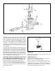
FIGURE 17 - TU-FLO® 400 AIR COMPRESSOR VERTICAL MOUNT - ENGINE LUBRICATED Straighten the prongs of the connecting rod bolt lock strap and remove the bolts and bearing caps. Push the piston with the connecting rods attached out the top of the cylinders of the crankcase. Replace the bearing caps on their respective connecting rods. Remove the piston rings from the pistons.
Press the crankshaft and ball bearings from the crankcase, then press ball bearings from crankshaft. Many compressors will have sleeve-type bearings in the crankcase or in the end cover. If the clearance between crankshaft journal and bearing exceeds .0065 in. the sleeve bearing should be replaced with appropriate undersize. CLEANING AND INSPECTION OF PARTS CLEANING All parts should be cleaned thoroughly in a good cleaning solvent before inspection.
CRANKCASE AND END COVERS Check for cracks or broken lugs in crankcase and end covers. Also check their oil passages to make sure they are open and clean. If an oil seal ring is used in the end cover, check fit of ring in ring groove. There should be 0.008 in. to 0.015 in. clearance at the gap when placed in the end bore of the crankshaft. If the oil ring is worn thin or is damaged, it should be replaced.
TU-FLO® 400 AIR COMPRESSOR CORRECT GROOVE CLEARANCE Used unloader mechanism should be replaced by unloader kits 265014 for Type Tu-Flo® 400 compressors and 265015 for Types Tu-Flo® 500 and 1000 compressors. The Tu-Flo® 1000 compressor requires two kits per compressor. .0015” .0030” The new unloader pistons should be a loose sliding fit in the unloader piston bores of the cylinder block. CORRECT GAP CLEARANCE WITH RING IN CYLINDER PARTS SPECIAL TO SELF-LUBRICATED TYPE COMPRESSORS .0035” .
Slightly worn or scratched inlet valves can be reclaimed by lapping them on a piece of fine crocus cloth on a flat surface, but it is suggested that new inlet valves be installed. ASSEMBLY INSTALLING CYLINDER BLOCK Position cylinder block gasket and block on crankcase according to markings made prior to disassembly. Using cap screws with lock washers, secure cylinder block to crankcase. Remove connecting bolts and bearing cap from one connecting rod.
BASEPLATE TESTING REBUILT COMPRESSOR SELF-LUBRICATED TYPE COMPRESSORS Install oil pump piston and rod on crankshaft. In order to properly test a compressor under operating conditions, a test rack for correct mounting, cooling, lubricating and driving the compressor is necessary. Such tests are not compulsory if the unit has been carefully rebuilt by an experienced person. Oil rod bearing fit must be the same as specified for connecting rod bearings.
3. Do not attempt to install, remove, disassemble or assemble a component until you have read and thoroughly understand the recommended procedures. Use only the proper tools and observe all precautions pertaining to use of those tools. 4. If the work is being performed on the vehicle’s air brake system, or any auxiliary pressurized air systems, make certain to drain the air pressure from all reservoirs before beginning ANY work on the vehicle.
MAINTENANCE INSTRUCTIONS FOR LARGE SUMP TU-FLO® 1000 AIR COMPRESSOR 288578 (SPECIAL APPLICATION) This compressor is an air-cooled, belt driven, self lubricated, V-four cylinder compressor. It is driven by an electric motor and cooling air is supplied by a fan on the driven pulley. The system air pressure is controlled between 135 psi and 150 psi by a pressure switch starting and stopping the electric motor.
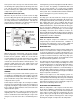
This troubleshooting guide obsoletes and supersedes all previous published troubleshooting information relative to Bendix air compressors. Advanced Troubleshooting Guide for Air Brake Compressors * The guide consists of an introduction to air brake charging system components, a table showing recommended vehicle maintenance schedules, and a troubleshooting symptom and remedy section with tests to diagnose most charging system problems.
Introduction to the Air Brake Charging System Powered by the vehicle engine, the air compressor builds the air pressure for the air brake system. The air compressor is typically cooled by the engine coolant system and lubricated by the engine oil supply.
Table A: Maintenance Schedule and Usage Guidelines Regularly scheduled maintenance is the single most important factor in maintaining the air brake charging system. Vehicle Used for: No. of Axles Column 1 Column 2 Typical Compressors Spec'd Discharge Line I.D. Length 1/2 in. 6 ft. Column 3 Recommended Air Dryer Cartridge Replacement1 Column 4 Recommended Reservoir Drain Schedule2 Column 5 Acceptable Reservoir Oil Contents3 at Regular Drain Interval e.g.
Air Brake Charging System Troubleshooting How to use this guide: Find the symptom(s) that you see, then move to the right to find the possible causes (“What it may indicate”) and remedies (“What you should do”). Review the warranty policy before performing any intrusive compressor maintenance. Unloader or cylinder head gasket replacement and resealing of the bottom cover plate are usually permitted under warranty. Follow all standard safety procedures when performing any maintenance.
Symptom: What it may indicate: What you should do: 2.0 Oil on the Outside of the Compressor Engine and/or other accessories leaking onto compressor. Find the source and repair. Return the vehicle to service. 2.1 Oil leaking at compressor / engine connections: (a)Leak at the front or rear (fuel pump, etc.) mounting flange. ð Repair or replace as necessary. If the mounting bolt torques are low, replace the gasket. (b)Leak at air inlet fitting. ð Replace the fitting gasket.
Symptom: What it may indicate: 4.0 Oil in Supply or Service Reservoir (air dryer installed) What you should do: Maintenance (a) If air brake charging system maintenance has not been (If a maintained Bendix performed.
Symptom: What it may indicate: 4.0 Oil in Supply or Service Reservoir* (air dryer installed) (continued) What you should do: Temperature (e) Air compressor discharge and/or air dryer inlet temperature too high. ð Check temperature as outlined in Test 3 on page 29. If temperatures are normal go to 4.0(h). (f) Insufficient coolant flow. ð Inspect coolant line. Replace as necessary (I.D. is 1/2"). ð Inspect the coolant lines for kinks and restrictions and fittings for restrictions. Replace as necessary.
Symptom: 4.0 Oil in Supply or Service Reservoir* (air dryer installed) (continued) What it may indicate: What you should do: Other (cont.) (i) Poorly filtered inlet air (poor air quality to compressor). Inspect the engine air cleaner. ð Check for leaking, damaged or defective compressor air inlet components (e.g. induction line, fittings, gaskets, filter bodies, etc.). Repair inlet components as needed. Note: Dirt ingestion will damage compressor and is not covered under warranty.
Symptom: What it may indicate: What you should do: 6.0 Excessive oil consumption in engine. A problem with engine or other engine accessory. ð See engine service manual. 7.0 Oil present at air dryer cartridge during maintenance. Air brake charging system is functioning normally. The engine service manual has more information. Oil shown leaking from an air dryer cartridge. 24 ð Air dryers remove water and oil from the air brake charging system. A small amount of oil is normal.
Symptom: 9.0 Air brake charging system seems slow to build pressure. (continued) What it may indicate: What you should do: (f) Restricted discharge line. ð If discharge line is restricted: ð By more than 1/16" carbon build up, replace the discharge line (see Table A, column 2, on page 18 for recommended size) and go to Test 3 on page 29. ð By other restrictions (e.g. kinks). Replace the discharge line. See Table A, column 2, on page 18 for recommended size. Retest for air build.
Symptom: 10.0 Air charging system doesn’t build air. What it may indicate: (a) Governor malfunction*. ð Go to Test 4 on page 30. (b) Restricted discharge line. ð See 9.0(f). (c) Air dryer heater malfunction: exhaust port frozen open. ð Replace air dryer heater. (d) Compressor malfunction. ð Replace the compressor only after making certain the preceding conditions do not exist.
Symptom: 12.0 Air dryer safety valve releases air. What it may indicate: What you should do: (a) Restriction between air dryer and reservoir. ð Inspect delivery lines to reservoir for restrictions and repair as needed. (b) Air dryer safety valve malfunction. ð Verify relief pressure is at vehicle or component manufacturer specifications. Replace if defective. (c) Air dryer performed. ð See Maintenance Schedule and Usage Guidelines (Table A, column 3, on page 18).
Symptom: 16.0 Compressor leaks air What it may indicate: (a) Compressor leaks connections or ports. at ð Check for leaking, damaged or defective compressor fittings, gaskets, etc. Repair or replace as necessary. ð Go to Test 6 on page 30. (c) Damaged gasket. head ð An air leak at the head gasket may indicate a downstream restriction such as a freezeup or carbon blockage and/or could indicate a defective or missing safety valve. Find blockage (go to 9.0(f) for details.) and then replace the compressor.
Tests Test 1: Excessive Oil Leakage at the Head Gasket Exterior leaks at the head gasket are not a sign that oil is being passed into the air charging system. Oil weepage at the head gasket does not prevent the compressor from building air. Observe the amount of weepage from the head gasket. If the oil is only around the cylinder head area, it is acceptable (return the vehicle to service), but, if the oil weepage extends down to the nameplate area of the compressor, the gasket can be replaced.
Tests (continued) Test 4: Governor Malfunction 1. Inspect control lines to and from the governor for restrictions (e.g. collapsed or kinked). Repair as necessary. 2. Using a calibrated external gauge in the supply reservoir, service reservoir, or reservoir port of the D-2™ governor, verify cut-in and cutout pressures are within vehicle OEM specification. 3. If the governor is malfunctioning, replace it. Test 5: Governor Control Line 1.
NOTES 31
Appendix A: Information about the BASIC Test Kit (Bendix P/N 5013711) Service writer records info - including the number of days since all air tanks were drained - and fills out symptom checklist. Technician inspects items. days Bendix® Air System Inspection Cup (BASIC) Test Information START BASIC TEST Park vehicle on LEVEL ground. Chock wheels, drain air from system. Drain contents of ALL air tanks into BASIC cup Is there less than one unit of liquid? Vehicle OK. Return vehicle to service.
Appendix A continued: Information about the BASIC Test Kit (Bendix P/N 5013711) ® Filling in the Checklist for the Bendix Air System Inspection Cup (BASIC) Test Note: Follow all standard safety precautions. For vehicles using a desiccant air dryer.
Appendix A continued: Information about the BASIC Test Kit (Bendix P/N 5013711) ® Filling in the Checklist for the Bendix Air System Inspection Cup (BASIC) Test Note: Follow all standard safety precautions. For vehicles using a desiccant air dryer. 2. Record amount of oil found: The Technician uses the chart (label) on the BASIC test cup to help decide the action to take, based on the amount of oil found.
Appendix B Technical Bulletin Bulletin No.: TCH-008-021 Subject: Effective Date: 11/1/92 Page: 1 of 2 Air Brake System - Cold Weather Operation Tips As the cold weather approaches, operators and fleets alike begin to look to their vehicles with an eye toward “winterization”, and particularly what can be done to guard against air system freeze-up. Here are some basic “Tips” for operation in the cold weather.
Appendix B: Continued Bulletin No.: TCH-008-021 Effective Date: 11/1/92 Page: 2 of 2 High Duty Cycle Vehicles (City Transit Coaches, Refuse Haulers, Etc.) The maximum discharge line length is 16 feet. Length I.D. min. Other Requirements 10-16 ft. ½ in. None If the discharge line length must be less than 10 feet or greater than 16 feet, contact your local Bendix representative.
Appendix B: Continued Technical Bulletin Bulletin No.: TCH-008-022 Subject: Additional Effective Date: 1/1/1994 Page: 1 of 1 Cold Weather Operation Tips for the Air Brake System Last year we published Bulletin PRO-08-21 which provided some guidelines for “winterizing” a vehicle air brake system. Here are some additional suggestions for making cold weather vehicle operation just a little more bearable.
BW1420 © 2004 Bendix Commercial Vehicle Systems LLC All rights reserved. 10/2004 Printed in U.S.A.