
Manual

10
CRANKCASE AND END COVERS
Check for cracks or broken lugs in crankcase and end covers.
Also check their oil passages to make sure they are open
and clean.
If an oil seal ring is used in the end cover, check fit of ring in
ring groove. There should be 0.008 in. to 0.015 in. clearance
at the gap when placed in the end bore of the crankshaft. If
the oil ring is worn thin or is damaged, it should be replaced.
Inspect oil ring groove in end cover; if groove is worn
excessively replace end cover or machine groove for next
oversize oil seal ring.
If the crankshaft main bearings are installed in the end cover,
check for excessive wear and flat spots and replace if
necessary.
CYLINDER BLOCK
Check for cracks or broken lugs on cylinder block. Also
check unloader bore bushings to be sure they are not worn,
rusted or damaged. If these bushings are to be replaced
they can be removed by running a 1/8 in. pipe thread tap
inside the bushing, then inserting a 1/8 in. pipe threaded rod
and pulling the bushing straight up and out. Do not use an
easy-out for removing these bushings.
INLET VALVES AND SEATS
If inlet valves are grooved or worn where they contact the
seat, they should be replaced. If the inlet valve seats are
worn or damaged so they cannot be reclaimed by facing,
they should be replaced.
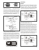
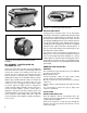
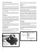
CYLINDER BORES
Cylinder bores which are scored or out of round by more
than 0.002 in. or tapered more than 0.003 in. should be
rebored or honed oversize. Oversize pistons are available in
0.010, 0.020, and 0.030 oversizes.
Cylinder bores must be smooth, straight and round.
Clearance between cast iron pistons and cylinder bores
should be between 0.002 in. minimum and 0.004 in.
maximum (Fig. 21).
PISTONS
Check pistons for scores, cracks or enlarged ring grooves;
replace pistons if any of these conditions are found. Measure
each piston with a micrometer in relation to the cylinder
bore diameter to be sure the clearance is between 0.002 in.
minimum and 0.004 in. maximum.
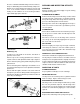
Check fit of wrist pins on pistons and connecting rod bushings.
Wrist pin should be a light press fit in pistons. If wrist pin is
loose fit, the pin, piston, or both should be replaced. Check
fit of wrist pin in connecting rod bushing by rocking the piston.
This clearance should not exceed 0.0015 in. Replace wrist
pin bushings if excessive clearance is found. Wrist pin
bushings should be reamed after being pressed into
connecting rods. Replace used wrist pin lock wires.
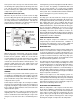
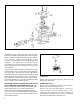
Tu-Flo
®
400 compressors manufactured after September
1977 will have Teflon plugs in each end of the wrist pins
instead of the lock wire. The Teflon plugs (pc. no. 292392)
may be used instead of the lock wires on all compressors.
See Fig. 22.
PISTON RINGS
Check fit of piston rings in piston ring grooves. Check ring
gap with rings installed in cylinder bores. Refer to Fig. 24
for correct gap and groove clearance.
All rings must be located in their proper ring grooves as
shown. The rings can be identified by the width and should
be installed with the bevel or the pipmark (if any) toward the
top of the piston. This applies to cast iron pistons (only as
shown above).
Die cast pistons use five (5) narrow rings.
FIGURE 21 - MEASURING CYLINDER BORES
FIGURE 22 - TU-FLO
®
400 AIR COMPRESSOR NEW STYLE
COMPRESSION
RINGS (2)
COMPRESSION
RINGS (2)