
Manual

5
PREVENTIVE MAINTENANCE
Regularly scheduled maintenance is the single most
important factor in maintaining the air brake charging system.
Refer to Table A in the Troubleshooting section for a guide to
various considerations that must be given to the maintenance
of the compressor and other related charging system
components.
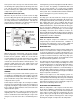
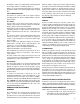
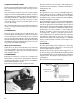
If the compressor is a self-lubricated type, its oil level should
be checked daily. The oil level should be kept between the
bottom of the dipstick threads and the bottom of the dipstick
(Fig. 13). Every 8,000 miles or 300 operating hours, the oil
should be drained and refilled with SAE 10-20-30.
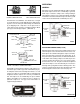
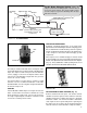
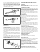
FIGURE 12A - SYSTEM DRAWING
Air Dryer
Reservoir Drain
Service Reservoir
(Supply Reservoir)
Compressor
Governor
(Governor plus Synchro valve
for the Bendix
®
DuraFlo
™
596
Compressor)
Discharge
Line
Optional “Ping” Tank
Optional Bendix
®
PuraGuard
®
QC
™
Oil Coalescing Filter
The Air Brake Charging System supplies the
compressed air for the braking system as well as other air
accessories for the vehicle. The system usually consists
of an air compressor, governor, discharge line, air dryer,
and service reservoir.
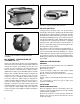
FIGURE 12B - DISCHARGE LINE SAFETY VALVE
HOLE
THREAD
The air dryer contains a filter that collects oil droplets, and a
desiccant bed that removes almost all of the remaining water
vapor. The compressed air is then passed to the air brake
service (supply) reservoir. The oil droplets and the water
collected are automatically purged when the governor
reaches its "cut-out" setting.
For vehicles with accessories that are sensitive to small
amounts of oil, we recommend installation of a Bendix
®
PuraGuard
®
QC
™
oil coalescing filter, designed to minimize
the amount of oil present.
COOLING
Tu-Flo
®
400, 500 or 1000 compressors may be air-cooled or
water- cooled and in some instances will have air-cooled
blocks and water-cooled heads. The air-cooled versions
are easily recognized by the external fins. The water-cooled
versions are cooled by vehicle coolant.
FIGURE 13 - OIL LEVEL - SELF-LUBRICATED
COMPRESSOR
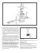
POLYURETHANE SPONGE STRAINER (Fig. 14)
Remove and wash all of the parts. The strainer element
should be cleaned or replaced. If the element is cleaned, it
should be washed in a commercial solvent or a detergent
and water solution. The element should be saturated in
clean engine oil, then squeezed dry before replacing it in
the strainer. Be sure to replace the air strainer gasket if the
entire air strainer is removed from the compressor intake.