
Manual

8
Straighten the prongs of the connecting rod bolt lock strap
and remove the bolts and bearing caps. Push the piston
with the connecting rods attached out the top of the cylinders
of the crankcase. Replace the bearing caps on their
respective connecting rods. Remove the piston rings from
the pistons. If the pistons are to be removed from the
connecting rods, remove the wrist pin lock wires or teflon
plugs and press the wrist pins from the pistons and
connecting rods.
If the pistons are removed from the rod, inspect the bronze
wrist pin bushing. Press out and replace the bushing if it is
excessively worn. (See Inspection of Parts.) Discard the
piston rings and the connecting rod journal bearings. Discard
the wrist pin bushings if they were removed. New Tu-Flo
®
400 compressors manufactured after approximately
September 1977 will have connecting rods without bearing
inserts. Repair size rods will have inserts.
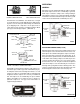
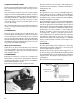
REMOVING AND DISASSEMBLING BASE PLATE
SELF-LUBRICATED TYPE COMPRESSORS (Fig. 18)
Remove screws that hold base plate. Remove base plate.
Remove oil relief valve set screw, then oil relief valve.
Remove oil strainer retaining ring and lift out oil strainer.
Unless it is necessary, the oil pump piston bushing should
not be removed. If necessary, remove the bushing set screw,
then bushing and shim.
Remove cotter pin from oil rod cap nuts, remove nuts, oil
pump piston rod and cap.
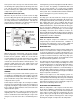
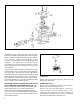
CRANKCASE (Fig. 19)
Remove end cover with oil seal, remove end cover gasket.
Replace oil seal after cleaning end cover.
Remove cap screws that hold opposite end cover to
crankcase; remove end cover and its gasket. Some
compressors have crankcases that have a shoulder for
positioning the crankshaft. In these cases the crankshaft
must be removed through one particular end.
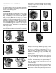
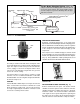
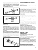
FIGURE 17 - TU-FLO
®
400 AIR COMPRESSOR VERTICAL MOUNT - ENGINE LUBRICATED
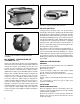
FIGURE 18 - BASE PLATE SELF-LUBRICATED TYPE
COMPRESSOR