
Manual

9
CLEANING AND INSPECTION OF PARTS
CLEANING
All parts should be cleaned thoroughly in a good cleaning
solvent before inspection.
CYLINDER HEAD ASSEMBLY
Remove all carbon deposits from discharge cavities and all
rust and scale from cooling cavities of cylinder head body.
Scrape all foreign matter from body surfaces and use air
pressure to blow dirt particles from all cavities.
Discharge valves can be dressed by lapping them on a piece
of fine crocus cloth on a flat surface, provided they are not
excessively worn.
CYLINDER BLOCK
Clean carbon and dirt from inlet and unloader passages.
Use air pressure to blow carbon and dirt deposits from
unloader passages.
Inlet valves, as in the case of discharge valves, not worn
excessively, can be cleaned by lapping them on a piece of
fine crocus cloth on a flat surface.
OIL PASSAGE
Clean thoroughly all oil passages through crankshaft,
connecting rods, crankcase, end covers and base plate. If
necessary, inspect passages with a wire and blow foreign
matter out with air pressure.
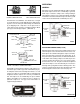
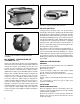
CRANKCASE - SELF-LUBRICATED TYPE
The breather should be thoroughly washed and cleaned.
The oil pump check valve in the base should be removed
and replaced. It is important when the oil pump check valve
is replaced that it be installed correctly with the ball stop pin
end pressed in first. When installed, the ball and its seat
should be visible from the crankcase base.
INSPECTION OF PARTS
CYLINDER HEAD BODY
Inspect cylinder head body for cracks or damage.
WATER-COO LED TYPE
Use air pressure to test water jackets of cylinder head and
block for leakage. Replace unit if leakage is found.
DISCHARGE VALVES AND SEATS
If discharge valves are worn and grooved where they contact
the seats, they should be replaced. If the discharge valve
seats are worn excessively so that there is no longer enough
metal left to reclaim them by lapping, the seats should be
replaced.
DISCHARGE VALVE SPRING AND CAP NUTS
Replace all used discharge valve springs and cap nuts.
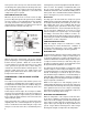
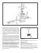
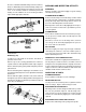
FIGURE 20 - CYLINDER BLOCK - EXPLODED VIEW
Press the crankshaft and ball bearings from the crankcase,
then press ball bearings from crankshaft. Many compressors
will have sleeve-type bearings in the crankcase or in the end
cover. If the clearance between crankshaft journal and
bearing exceeds .0065 in. the sleeve bearing should be
replaced with appropriate undersize.
BLOCK (Fig. 20)
If compressor is fitted with an air strainer, inlet elbow or
governor, remove same.
Remove cap screws securing cylinder block to crankcase;
separate crankcase and cylinder block and scrape off gasket.
Remove unloader spring, spring saddle and spring seat from
cylinder block.
Remove unloader guides and plungers and, with the use of
shop air, blow unloader pistons out of cylinder block unloader
piston bores.
Remove inlet valve guides; inlet valve seats can be removed
but only if they are worn or damaged and are being replaced.
Unloader bore bushings should be inspected but not removed
unless they are damaged.
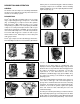
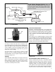
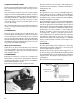
FIGURE 19 - CRANKCASE - TU-FLO
®
400 & 500 AIR
COMPRESSORS
FIGURE 19A - CRANKCASE - TU-FLO
®
1000 AIR
COMPRESSOR