
Owner's Manual


1110
SMARTIRE SYSTEMS INC.
Installation
TRANSMITTER INSTALLATION
Caution: Qualified personnel must perform the following installation procedures
that highlight the steps required to ensure that the Transmitters are properly
installed and undamaged. It does not include any standard procedures normally
required in the process of replacing a tire (i.e. lubrication, proper inflation and
deflation procedures and any other procedures deemed necessary by the tire
manufacturer or dealer).
The equipment and images in this manual use one manufacturer’s tire changer
and may not apply to you.
TOOLS REQUIRED
• Tire changing equipment
• Tire balancing equipment
• Hexagon socket and driver (
5
/
16
”or 7mm)
• Metal cutter
• Torque wrench
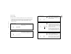
INSTALLING TRANSMITTER ON A WHEEL
Shorten the strap by cutting to the appropriate length for the wheel diameter
used (see chart). Remove burrs from strap end.
Nominal wheel size (inches)
15 16 17 18 19 20 21 22 23
Cut-off length (inches)
28 25 22 19 15 12 9 6 3
Cut-off length (cm)
71 64 56 48 38 30 23 15 8
Below is the suggested installation
sequence for use with optional Full
Function Display.
Transmitter Wheel Position
Green Right front
Red Left front
Blue Right rear
Yellow Left rear
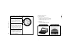
The base of the drop centre well must
be flat and wide enough to allow the
Transmitter to contact the rim over its
complete width.
(see Fig.2)
• Pass strap through Transmitter as shown.
• Position the Transmitter in the lowest
area of the drop centre well near the
valve.
(see Fig.3)
• Attach the strap end to the clamp
by advancing the wormgear with the
socket driver. Tighten to 35 inch
pounds (4 N-m).
• Cut off excess strap length to approxi-
mately one inch (25 mm) from the
wormgear.
FIG.1
FIG.2
FIG.3