SmarTire Systems Inc.
SmarTire Systems Inc. Tire Monitoring System Reference Manual Table of Contents FCC Notice...................................................................................................................................5 Introduction .................................................................................................................................6 Purpose of Manual....................................................................................................................
SmarTire Systems Inc. Tire Monitoring System Reference Manual Operation................................................................................................................................. 24 Programming the Receiver.................................................................................................... 24 Multi-function Display (MFD) ................................................................................................25 Controls and Display ...............................
SmarTire Systems Inc. Tire Monitoring System Reference Manual LCD cable end connection ................................................................................................................................................ 49 Power Shoe Installation.......................................................................................................... 49 Connection to External Systems ............................................................................................
SmarTire Systems Inc. Tire Monitoring System Reference Manual FCC Notice This device complies with Part 15 of the FCC Rules. Operation is subject to the following two conditions: (1) this device may not cause harmful interference, and (2) this device must accept any interference received, including interference that may cause undesired operation. This equipment has been tested and found to comply with the limits for a Class B digital device, pursuant to Part 15 of the FCC Rules.
SmarTire Systems Inc. Tire Monitoring System Reference Manual Introduction Purpose of Manual This manual is intended for use by service personnel and dealers. It contains detailed information on operation, installation and service of the SmarTire Pressure Monitoring Systems (GEN-II). About Tire Monitoring Systems The SmarTire System consists of a receiver and optional programmable Multifunction Display, which are conveniently mounted within easy view and reach of the driver.
SmarTire Systems Inc.
SmarTire Systems Inc. Tire Monitoring System Reference Manual System Scope of Use and Warnings The SmarTire™ System and Tire Maintenance This system is a sensing device designed to identify and display tire operating data and activate an alert or warning when pressure or temperature irregularities are detected. It is the responsibility of the driver to react promptly and with discretion to alerts and warnings. Abnormal tire inflation pressures should be corrected at the earliest opportunity.
SmarTire Systems Inc. Tire Monitoring System Reference Manual 5. The high temperature warning indicates that the contained air temperature has exceeded the selected maximum. A tire temperature buildup can be caused by a number of factors including severe under inflation, hard sustained braking, vehicle overload and sustained high speeds.
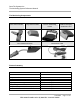
SmarTire Systems Inc. Tire Monitoring System Reference Manual SmarTire Product Overview The Tire Monitoring Systems are sold in several configurations and options. Below is a table outlining the available kits, upgrades and spare components. Product List Product Product Stock Code Description A 060.1004 H B 060.1002 060.2004 I 060.2002 D E C 061.4000 061.4001 061.3000 F 061.1002 G 061.
SmarTire Systems Inc. Tire Monitoring System Reference Manual Tire Monitor System Kit Component Table H 060.1002 B 060.2004 I 060.2002 D 061.4000 E 061.4001 C 061.3000 F 061.1002 G 061.2002 063.2000 063.2001 063.2002 063.2003 Pressure Alert System – 4 wheels – Multi fit Strap Mount Transmitters Pressure Alert System – 2 wheels – Multi fit Strap Mount Transmitters Pressure Alert System – 4 wheels - Valve Transmitters (valves not incl.
SmarTire Systems Inc. Tire Monitoring System Reference Manual System Descriptions Pressure Alert Systems – 2 and 4 wheels – Multi-fit Strap Mount Transmitters Kit # 060.1004 Kit # 060.1002 (4 wheel) Product A (2 wheel) Product H Overview These kits contain a base receiver, two or four strap mounted transmitters, installation hardware and documentation for use on tires with a pressure up to 83 PSI (gauge). The transmitters transmit pressure and temperature data when the vehicle attains a speed of 10 kph.
SmarTire Systems Inc. Tire Monitoring System Reference Manual Bill of Materials 060.1004 Pressure Alert Systems – 4 wheels – Multi-fit Strap Mount Transmitters QTY PER STOCK CODE Description 1 1 1 4 4 1 1 1 1 069.0001 069.0002 200.0059 200.0064 264.0115 276.0041 276.0042 INSTALLATION KIT POWER CABLE KIT RECEIVER -BASE-GENII TRANSMITTER-STRAP-GENII STRAP - STAINLESS STEEL CLAMP BOX - PRODUCT KIT BOX - ELECTRONIC PARTS 276.0043 700.0000 BAG TRANSMITTER SHIELD DOCUMENT KIT, GENII - BASIC 060.
SmarTire Systems Inc.
SmarTire Systems Inc. Tire Monitoring System Reference Manual Pressure Alert Systems – 2 and 4 wheels – Multi-fit Valve Mount Transmitters Kit # 060.2004 (4 wheel) Product B Kit # 060.2002 (2 wheel) Product I Overview These kits contain a base receiver, two or four valve mounted transmitters, installation hardware and documentation for use on tires with a pressure up to 83 PSI (gauge). The transmitters transmit pressure and temperature data when the vehicle attains a speed of 10 kph.
SmarTire Systems Inc. Tire Monitoring System Reference Manual Bill of Materials 060.2004 Pressure Alert Systems – 4 wheels – Multi-fit Valve Mount Transmitters QTY PER STOCK CODE Description 1 1 1 4 1 1 1 069.0001 069.0002 200.0059 200.0065 276.0042 276.0043 700.0000 INSTALLATION KIT POWER CABLE KIT RECEIVER -BASE-GENII TRANSMITTER-STRAP-GENII BOX - ELECTRONIC PARTS BAG TRANSMITTER SHIELD DOCUMENT KIT, GENII - BASIC 060.
SmarTire Systems Inc.
SmarTire Systems Inc. Tire Monitoring System Reference Manual Pressure Alert Full Function Display Kit # 061.4000 LCD-I Kit # 061.4001 LCD-R Overview The full function display is used with any existing system to extend the functionality of the basic tire pressure monitoring system up to 20 tire positions. It provides a digital pressure and temperature readout as well as diagnostic data such as transmitter battery life for each tire.
SmarTire Systems Inc. Tire Monitoring System Reference Manual Bill of Materials 061.4000 Pressure Alert Full Function Display – Type I QTY PER STOCK CODE 1 200.0060 LCD DISPLAY UNIT - TYPE I 1 276.0042 1 700.0001 Description BOX - ELECTRONIC PARTS DOCUMENT KIT, GENII - LCD 061.4001 Pressure Alert Full Function Display – Type R QTY PER STOCK CODE 1 200.0060 LCD DISPLAY UNIT - TYPE I 260.0096 CABLE REMOTE LCD 1 276.0042 1 700.
SmarTire Systems Inc. Tire Monitoring System Reference Manual Pressure Alert Flexible Power Adaptor Kit # 061.3000 Overview A flexible power adapter is plugged into the cigarette lighter socket and the receiver is mounted on it so that it can be positioned by the driver for the best viewing position. Bill of Materials 061.3000 Pressure Alert Flexible Power Adaptor QTY PER STOCK CODE Description 1 200.0066 POWER SHOE ASSY-GOOSENECK-GII 1 276.
SmarTire Systems Inc. Tire Monitoring System Reference Manual Pressure Alert Transmitter Kit – 2 - Multi-fit Strap Mount Transmitters Kit # 061.1002 Overview This kit consists of two strap-mount transmitters and installation hardware and instructions for installation. It is intended to expand an existing installation. Note: If this kit increases the total number of transmitters on a vehicle to greater than four, then the full function display must also be installed to view all tire positions.
SmarTire Systems Inc. Tire Monitoring System Reference Manual Pressure Alert Transmitter Kit – 2 - Multi-fit Valve Mount Transmitters Kit # 061.2002 Overview This kit consists of two strap-mount transmitters and installation hardware and instructions for installation. Note: If this kit increases the total number of transmitters on a vehicle to greater than four, then the full function display must also be installed to view all tire positions. Bill of Materials 061.
SmarTire Systems Inc. Tire Monitoring System Reference Manual Pressure Alert Valve Kits Overview These kits consist of two alligator valves of differing length for use with valve-mount transmitter kits. Component Image Pressure Alert 2 Valve Kit – A Kit stock code 063.2000 Pressure Alert 2 Valve Kit – B Kit stock code 063.2001 Pressure Alert 2 Valve Kit – C Kit stock code 063.2002 Pressure Alert 2 Valve Kit – D Kit stock code 063.
SmarTire Systems Inc. Tire Monitoring System Reference Manual Receiver Operation Ensure the receiver is plugged in. After power is applied the lights flash red, green, then amber. They continue to flash amber until signals are received from the tire transmitters which transmit pressure data shortly after the vehicle starts to move (at speeds greater than 10kph).. Then all will turn off except the system light (left most light). The receiver is preset to initiate warnings at two levels of tire pressure.
SmarTire Systems Inc.
SmarTire Systems Inc.
SmarTire Systems Inc. Tire Monitoring System Reference Manual Multi-function Display Operation Modes The Multi-function display extends the functionality of the basic tire monitoring system from four to twenty wheel positions. Digital readouts for pressure, temperature and temperaturecompensated pressure alerts are provided for each wheel position.
SmarTire Systems Inc. Tire Monitoring System Reference Manual Stand-By Mode The stand-by mode is the state of the multi-function display showing the system status, i.e. whether or not data has been received from installed transmitters. The screen is blank if no data has been received from any transmitter. A button must be pressed in this mode to enter the other modes. Specific data for a selected wheel position is obtained in the regular mode. • No data has been received from any installed transmitter.
SmarTire Systems Inc. Tire Monitoring System Reference Manual Programming Modes Standard Operating Settings – Level 1 • • • • • • Cold Pressure Tire Rotation Low Pressure Warning Pressure Deviation Temperature Alert Units Selection To Enter Programming Mode 1. 2. 3. 4. 5. Enter Standby mode Press Set button Cold Pressure Program mode is entered Use MODE button to scroll the possible settings. Press Set button to get back into Standby mode.
SmarTire Systems Inc. Tire Monitoring System Reference Manual Cold Inflation Pressure This function changes the cold inflation pressure for each axle. • To choose this mode press the TIRE button when the pressure unit and the snowflake icon are displayed. • Press the TIRE button to scroll to the desired axle. The tires of the selected axle are filled in. • Press the MODE button to view the current value. • Press the TIRE or MODE button to increase and decrease the value respectively.
SmarTire Systems Inc. Tire Monitoring System Reference Manual Tire Rotation After a tire rotation the receiver needs to be reconfigured to accept existing tire ID numbers from the new locations. The color code on the transmitter and valve correspond to a sensor number (ID 1 programmed in two locations) • To choose this mode press the TIRE button when the tire rotation icon is displayed • The tire outline indicates the installed sensors. The selected tire location is filled-in.
SmarTire Systems Inc. Tire Monitoring System Reference Manual Low-Pressure Warning This function changes the low-pressure warning threshold for each axle. • To choose this mode press the TIRE button when the flat tire icon and the pressure unit are displayed. • The tires of the selected axle are filled in. Use the TIRE button to scroll to the desired axle. • Press the MODE button to select the axle. The current value is shown.
SmarTire Systems Inc. Tire Monitoring System Reference Manual Pressure Deviation Alert This function sets the pressure deviation alert threshold for all tires. • To choose this mode press the TIRE button when the +/icon and the pressure unit are displayed. • Press the TIRE button to display the current value. Press the TIRE or MODE buttons to increase or decrease the value respectively. • Press the MODE button until the display shows OFF to disable this feature.
SmarTire Systems Inc. Tire Monitoring System Reference Manual High Temperature Alert Change or turn off the high-temperature alert threshold in this mode. • To choose this mode press the TIRE button when the alert icon and the temperature unit are displayed. The current value of High Temperature Alert is displayed. Press the TIRE or MODE button to increase or decrease the value respectively. The minimum level is 86º F.
SmarTire Systems Inc. Tire Monitoring System Reference Manual Diagnostic Modes - Level 2 The following modes are found under the Diagnostic menu, which are accessed by holding the SET button in Stand-By mode or Programming menu for 5 seconds. The MODE button is used to scroll through each diagnostic mode.
SmarTire Systems Inc. Tire Monitoring System Reference Manual Battery Condition Use this mode to check the battery voltage level for each transmitter. • To view the transmitter battery voltage for a specific wheel location press the TIRE button to scroll to each location. • If there is no voltage data received for a transmitter “---“ is displayed. • Press the SET button to exit this mode.
SmarTire Systems Inc. Tire Monitoring System Reference Manual Learn This mode is used to add or remove transmitters from the system. • Press the MODE button to select the learn mode icon. The currently installed positions are indicated with the tire outlines. • Press the TIRE button to display the ten possible wheel positions for the towing vehicle. The currently installed transmitter positions are now indicated with a filled in tire indicator.
SmarTire Systems Inc. Tire Monitoring System Reference Manual Hidden Programming Mode – Level 3 Low Pressure Alert This mode sets the Low Pressure Alert and is used only by the receiver. Hold the SET button for 10 seconds. The screen will show the diagnostic menu after 5 seconds. Another 5 seconds later, the warning icon and the pressure unit are displayed • Use the TIRE button to scroll to the desired axle. The tires of the selected axle are filled in.
SmarTire Systems Inc. Tire Monitoring System Reference Manual Checking Tire Conditions Startup When power is applied a single beep accompanies all ICONS and lights turning on. Then screen blanks and only button lights stay on green. Vehicle motion initiates data transmission from the wheel transmitters. The MFD windshield symbol (and louver) turn on, followed by each of the tire position icons. The windshield symbol indicates that data is coming from the towing vehicle transmitters.
SmarTire Systems Inc. Tire Monitoring System Reference Manual Detecting Abnormal Tire Pressure The MFD alerts the driver of abnormal tire pressure with a Pressure Deviation Alert or a Low Pressure Warning. Understanding Temperature Compensated Pressure Readings An important feature of the SmarTire (MFD) system is that pressure alerts are initiated from a temperature compensated pressure calculation rather than on the actual pressure read by the sensor.
SmarTire Systems Inc. Tire Monitoring System Reference Manual Pressure Deviation Alert The Pressure Deviation Alert is initiated when the actual pressure of a tire deviates by more than the amount programmed for the vehicle. For example this will occur if the MFD is set for +- 2 PSI and the actual pressure drops to 24 PSI (from the required pressure of 34 PSI). • • Low Pressure Warning The MFD issues one beep. The alarm light and alert icon flash on and off.
SmarTire Systems Inc. Tire Monitoring System Reference Manual Detecting Excessive Tire Air Temperature High Temperature Warning The High Temperature Alert is initiated when the temperature from a transmitter exceeds the programmed setting.
SmarTire Systems Inc. Tire Monitoring System Reference Manual Installation Valve Mount Transmitter Procedure Overview 1. 2. 3. 4. Deflate and demount the tire. Verify that the wheel can accept a valve mount transmitter Install the transmitter. Mount the tire and inflate to the proper pressure. Alligator Valve Selection Process and Verification of Proper Assembly Fit Internal Visual Inspection of the Wheel or Rim 1.
SmarTire Systems Inc. Tire Monitoring System Reference Manual 5. • • • • Confirm maximum rim thickness at valve clamping area: Is it 0.156” (4MM)? [Normally not a problem with a 0.453” diameter valve hole] – If greater, then use the strap mount sensor. If less, then continue. 6. • • • Confirm depth of the drop-center well near the valve hole: Is it 0.67” (17.3MM) below the humps of the bead seats? If shallower/deeper, then consider using the strap mount sensor. If OK, then continue. 7.
SmarTire Systems Inc. Tire Monitoring System Reference Manual 1. Start by using the valve assembly with longest of the three bases (Alligator #59.0054) 2. Remove the sensor attachment screw and install the valve body (into valve hole from the front side), washer and nut. Finger-tighten the nut until grommet is evenly seated. Make sure the fit of the valve body/grommet and the clearance of the washer/nut with respect to wheel. 3.
SmarTire Systems Inc. Tire Monitoring System Reference Manual 8. Finally, clearance between the sensor body and the side of the wheel’s drop-center well should be at least 0.040” (1MM), and the housing contact pads at each end of the sensor housing are seated against the base of the drop-center well. 9. Install appropriate colored washer onto valve stem if required.
SmarTire Systems Inc. Tire Monitoring System Reference Manual Strap Mount Transmitter Process Overview 1. 2. 3. 4. 5. Ascertain that the wheel can accept a strap mount transmitter. Deflate and demount the tire. Install the transmitter Mount the tire. Inflate the tire to the proper pressure.
SmarTire Systems Inc. Tire Monitoring System Reference Manual Base Receiver Installation The receiver needs an electrical connection to the vehicle 12 volt power and it needs to be attached somewhere within view of the driver. The power connection may be made with the power cable supplied with every receiver or by using the gooseneck power adapter. The only consideration to watch for is that the receiver turns on when the vehicle is started.
SmarTire Systems Inc. Tire Monitoring System Reference Manual LCD unit Installation The LCD unit comes in two models, one which integrates into the base receiver by clipping to its front panel and other type which is connected remotely to the receiver via a 6’ cable. To install the either LCD type, first remove the front bezel of the base receiver. Plug the LCD-I type in place of the bezel.
SmarTire Systems Inc. Tire Monitoring System Reference Manual Connection to External Systems Interface; IPC to RS232 GEN II BATTERY CONNECTOR PIN DESIGNATIONS Battery connector as seen from the rear of PCB. PIN # DESIGNATIONS 1 2 3 4 5 6 7 8 9 10 Open collector output (P2-4) - Diagnostic E-I2C-CLK Communication (Clock) Open collector output (P2-2) – Pressure alert E-I2C-DAT Communication (Data) No Connection No Connection Vin (supply voltage) Ground Battery pack input (4.
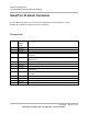
SmarTire Systems Inc. Tire Monitoring System Reference Manual Technical Specifications Base Receiver Power Consumption Operating Temperature Range Storage Temperature Range Frequency Size Weight Operating Humidity Number of indicators 125 ma. maximum during alert -40° F to 185° F (-40° C to 85°C) -40° F to 185° F (-40° C to 85° C) 433.92 MHZ ± 75 kHz 2.85” H x 3.08” D x .
SmarTire Systems Inc. Tire Monitoring System Reference Manual Transmitters – Strap Mount Battery Life (Projected) Operating temperature range Storage temperature Range Operating humidity Data transmitted Data transmission rate Weight Size Frequency Pressure Range Pressure accuracy Temperature accuracy Start-stop mode Method of mounting 8.
SmarTire Systems Inc. Tire Monitoring System Reference Manual Service and Warranty Replacing a Transmitter – Valve and Strap Mount 1. 2. 3. 4. 5. Remove the existing transmitter Install the new transmitter using the installation procedure in this manual. Set the multi-function display into learn mode. Spin the tire to provoke transmission. Verify the system functions properly. Replacing a Receiver 1. Unplug the existing receiver 2. Plug in a multi-function display and set into learn mode 3.
SmarTire Systems Inc. Tire Monitoring System Reference Manual Limited Warranty (US) NOTE: This warranty statement is currently under revision. This Warranty covers substantial manufacturer’s defects in workmanship and materials. It does not cover any unit that is damaged beyond normal usage, was not properly installed, was subjected to chemical contact, or other acts or omissions not sanctioned by the Owner’s Manual.
SmarTire Systems Inc. Tire Monitoring System Reference Manual Warranty (Canada) NOTE: This warranty statement is currently under revision. This Warranty covers substantial manufacturer’s defects in workmanship and materials. It does not cover any unit that is damaged beyond normal usage, was not properly installed, was subjected to chemical contact, or other acts or omissions not sanctioned by the Owner’s Manual.
SmarTire Systems Inc. Tire Monitoring System Reference Manual Regulatory Requirements North American Regulatory Requirements For the US, FCC notice is required. See notice at beginning of manual. For Canada, Canadian Regulatory number Other – use FCC notice. European Requirements To be determined on a country by country procedure.