The Air Brake Handbook ©2004 Bendix Commercial Vehicle Systems LLC • All Rights Reserved
The Air Brake Handbook ©2004 Bendix Commercial Vehicle Systems LLC • All Rights Reserved www.bendix.
Device Index Device Index F A ™ A-18 Controller Assy. . . . . . . . . . . Actuators . . . . . . . . . . . . . . . . . . . . . AD-2™ Air Dryer . . . . . . . . . . . . . . . AD-4™ Air Dryer . . . . . . . . . . . . . . . AD-9™ Air Dryer . . . . . . . . . . . . . . . AD-IP™ Air Dryer . . . . . . . . . . . . . . AD-IS™ Air Dryer Module . . . . . . . . AD-SP™ Air Dryer . . . . . . . . . . . . . . AF-3™ In-line Air Filter . . . . . . . . . . Air Disc Brakes . . . . . . . . . . . . . . . .
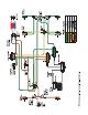
Handbook Section Index How to use the Air Brake Handbook This nine-section handbook provides an introduction to the use and operation of Bendix air brake systems and devices. Components are introduced and shown with typical system diagrams to show where they are used. As new components are introduced and their function explained, they gradually build up to a complete functioning air brake system. Partial system-drawings, throughout the manual, assist in explaining of the use of the components.
General Precautions IMPORTANT The systems presented in this manual are intended for illustrative purposes only and are not intended to be used for actual vehicle piping. Air Brake System General Precautions WARNING! PLEASE READ AND FOLLOW THESE INSTRUCTIONS TO AVOID PERSONAL INJURY OR DEATH: When working on or around a vehicle, the following general precautions should be observed at all times. 1. Park the vehicle on a level surface, apply the parking brakes, and always block the wheels.
Introduction Section 1: One-Page Introduction Air Supply The vehicle’s compressor takes in filtered air, either at atmospheric pressure from the outside (or already at an increased pressure, from the engine turbocharger in some cases), and compresses it. The compressed air is delivered to the air dryer where water and a small amount of oil is removed.
Overview Section 2: The Charging System The charging system consists of: • An air compressor • A governor, to control when the compressor needs to build, or stop building, air for the system and also to control the air dryer purge cycle • An air dryer, to remove water and oil droplets from the air • Reservoirs (or “air tanks”) to store air to be used for vehicle braking, etc.
Compressors drops to the “cut-in” setting of the governor, the governor returns the compressor back to building air and the air dryer to air drying mode. As the atmospheric air is compressed, all the water vapor originally in the air is carried along into the air system, as well as a small amount of the compressor lubricating oil as vapor. The duty cycle is the ratio of time the compressor spends building air to the total engine running time.
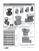
Compressors Single-Cylinder Compressors Two-Cylinder Compressors BX-2150™ air compressor Tu-Flo® 700 air compressor Tu-Flo® 501 air compressor Tu-Flo® 500 air compressor Tu-Flo® 400 air compressor BA-921™ air compressor nd lu En ers br g i Tu icat ne/ rb ed se lf o in ava le i t l.? co Wa opt ol te ion ed r/ ? av airail .
Compressor Maintenance Guidelines Maintenance Schedule and Usage Guidelines Regularly scheduled maintenance is the single most important factor in maintaining the air brake charging system. The table below is an introduction to the maintenance intervals for air brake charging systems. See your compressor and/or air dryer Service Data sheet for more information. If you are concerned that a compressor may be passing oil, use the BASIC™ Test Kit: Order Bendix P/N 5013711. Low Air Use Low Air Use e.g.
Governors and Components Governors and Components The Governor monitors the air pressure in the supply reservoir and operates the compressor unloading mechanism to control whether the compressor builds air pressure or not. The Bendix® D-2™ governor is an adjustable pistontype valve available preset to a choice of pressure settings.
Reservoirs and Components Reservoirs (or “air tanks”) serve the air brake system as a storage tank for compressed air. The reservoir size is selected by the vehicle manufacturer to provide an adequate amount of air for use by the braking system and other control devices. Bendix reservoirs are built in accordance with SAE specifications and are available in various sizes in both single and double compartment design configurations, and are certified to comply with government regulations (such as FMVSS 121).
Air Dryers Air Dryers The air dryer is an in-line filtration system that removes both water vapor and oil droplets from the compressor discharge air after it leaves the compressor. This results in cleaner, drier air being supplied to the air brake system, and aids in the prevention of air line and component freeze-ups in winter weather. Air dryers typically use a replaceable cartridge containing a desiccant material and an oil separator.
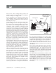
Air Dryers and Filters AD-SP™ Air Dryer SC-PR™ Valve (installation uses SC-PR™ valve) The AD-SP™ air dryer uses a small amount of air from the supply and front axle (secondary) reservoirs to perform the purge function. Because of this difference, the AD-SP™ air dryer is smaller and lighter than air dryers that have their purge volume within the dryer canister. An SC-PR ™ Single Check Protection Valve is used in conjunction with the AD-SP™ air dryer.
Miscellaneous Charging System Related Components A double check valve is used in the air system when a single function or component must receive air from, or be controlled by, the higher of two sources of pressure. An internal disc or shuttle moves in response to the higher air pressure and allows that air source to flow out of the delivery port. It is recommended that double check valves be mounted so that the shuttle (or disc) operates horizontally.
Dual Circuit Brake Valves Section 3: The Control System The control system typically consists of: • Vehicle parking using push-pull hand operated • A foot brake valve and often an additional handoperated trailer brake control valve valves and spring brakes, • Anti-compounding system design to prevent both • Brake actuators or rotochambers, to change the applied air pressure into a push-rod force which operates the foundation brakes (air disc, S-Cam, etc.
Dual Circuit Brake Valves, continued (See ABS section for more about modulators) Mostly used in the transit (buses/coaches) industry, the E-10PR™ retarder control brake valve has circuitry that is used to communicate with retarder systems installed on automatic transmission vehicles - extending the life of brake system components. Hand-operated Brake Valves For information on trailer control hand-operated valves, see page 29.
Actuators Actuators Brake Chamber Actuators convert the air pressure being applied into a mechanical push-rod force acting on the foundation brakes. Air enters the actuator and pressurizes a chamber containing a rubber diaphragm. The air pushes against the diaphragm, pushing against the return spring and moving the push-plate (and push-rod) forward.
Slack Adjusters Slack Adjusters The slack adjuster is the link between a brake chamber or actuator and the S-Cam brake camshaft. Its arm is fastened to the push rod with a yoke and its spline is installed on the foundation brake cam shaft. It transforms and multiplies the force developed by the chamber into a torque which applies the brakes via the brake camshaft.
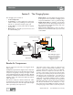
Foundation Brakes Brake Chamber Spider Slack Adjuster Axle AIR DISC BRAKE Brake Drum CAM Rotor Shoe S-CAM BRAKE Friction Material Foundation Brakes The foundation brake is the actual braking mechanism located at each end of the axle. It generally consists of an air or spring brake chamber (with slack adjuster for S-Cam), and a mechanical brake mechanism including the friction material.
Foundation Brakes, continued Brake lining and block differ in that it takes two brake blocks to line one shoe while a single brake lining segment is all that is required to do the same job. Block is generally 3/4" thick and used on class 8 vehicles while lining is 1/2" thick and generally used on smaller vehicles. While it is recommended that a matching set of lining be used on each wheel, under some conditions a combination of different lining materials may be desirable.
Quick Release, Ratio Valves Quick Release Valves The function of the quick release valve is to speed up the exhaust of air from the air chambers. It is mounted close to the chambers it serves. In its standard configuration, the valve is designed to deliver within one psi of control pressure to the controlled device; however, for special applications the valve is available with greater differential pressure designed into the valve.
Ratio, Proportioning Valves Bobtail Ratio Valves The LQ-5™ bobtail ratio valve is used on the front (steering) axle of tractor air brake systems to reduce brake application pressure during normal tractor-trailer operation. During bobtail mode (when the tractor is not pulling a trailer), tractor braking performance is improved because the LQ-5™ bobtail ratio valve delivers full brake pressure to the steering axle.
Relay Valves Relay Valves Relay valves are primarily used on vehicles to apply and release rear axle(s) service or parking brakes. When the driver applies the brakes, air travels through the delivery (in this case signal) line to the relay valve and moves an internal piston down. This closes the exhaust and opens the delivery of air to the brakes.
Push-Pull Valves Push-Pull Control Valves Push-pull control valves are most often mounted on the vehicle dash board and are used for a variety of control applications. The PP-1™ and PP-2™ valves are pressure sensitive, normally closed, on/off control valves which automatically return to the exhaust (button out) position when supply pressure is below the required minimum. They may be manually operated to either position when pressure is above the required minimum.
Spring Brake Valves Spring Brake Valves The SR-1™ spring brake valve is used in dual circuit brake systems and serves two functions; during normal operation, it limits hold-off pressure to the spring brakes to 90 or 95 psi. If a loss of pressure occurs in the rear service brake service supply, the valve will provide a modulated spring brake application, proportional to the driver’s service braking pressure delivered to the front axle.
Lever Operated Control Valves Lever Operated Control Valves The TW-2 ™ and TH-3 ™ valves are identical in appearance (and similar to the TW-1™, TW-3™ and TW-4™) except they have two control valves housed in a single body. These two valves differ by the internal cammed control lever, which for the TW-2™ control valve has two lever positions, while the TH-3™ valve has three.
Miscellaneous Control Valves Miscellaneous Control Valves Inversion valves are air operated control valves, and unlike most control valves are normally open, i.e. without control pressure the supply is common to the delivery. The inversion valve is closed by using air pressure from another source and is primarily used in emergency or parking brake systems which operate with air from an isolated reservoir.
Tractor/Trailer Parking and Emergency Systems Section 4: Tractor Parking,Trailer Charging/Parking and Emergency Systems The tractor/trailer parking and emergency system typically consists of: • The tractor parking control system • The trailer parking and emergency system, and • The tractor protection system Miscellaneous Charging System Components See the inside front cover for system schematic.
Dash Control Modules The MV-3™ dash control module combines the functions of a PP-1™ control valve and a PP-7™ trailer supply valve together into a unified device. Tractor Service Reservoir #1 Exhaust Port Supply #1 Auxiliary Delivery Port Delivery The Bendix® MV-3™ dash control module is a twobutton, push-pull control valve housed in a single body which includes a dual circuit supply valve and a check valve.
Tractor Protection Valves Tractor Protection Valves The primary function of tractor protection valves (e.g. the TP-3™ tractor protection valve) is to protect the tractor air brake system under trailer breakaway conditions and/or conditions where severe air leakage develops in the tractor or trailer. In addition, in everyday use, the valve is used to shut off the trailer service and supply lines before disconnecting the tractor from the trailer.
Trailer Spring Brake Valves SR-2™ Spring Brake Valve Trailer Spring Brake Valves Trailer spring brake valves are designed for use in trailer air brake systems. The SR-4™ trailer spring brake valve was an earlier design that used a dedicated spring brake reservoir for release of the trailer spring brakes. Note: This valve is available for service only, due to changes made in FMVSS 121 (superceded by SR-5™). All other Bendix spring brake valves use service reservoir air for trailer spring brake release.
Trailer Spring Brake Valves, continued Service Reservoir Typical SR-5™ Trailer Spring Brake Valve Tandem Axle Trailer Air System (Note simplified system plumbing) ABS Controller/ Relay Assembly The TE-1™ trailer emergency stop light switch is a pressuresensitive switch to operate the stop lights in the event of emergency trailer brake application.
Trailer/Converter Dolly Brakes Section 5: Converter Dolly Brakes Typical components found in a converter dolly brake system are shown in this section. See the inside front page for full system schematic. System Schematic (Without ABS. ABS currently required for most applications.
Trailer/Converter Dolly Brakes Typical Converter Dolly Components The R-8P™ and R-12P™ pilot relay valves are special purpose relays designed specifically for use on trailers and converter dollies. These 0 p.s.i. crack and differential relays speed up brake application signals to provide an equal or balanced pressure signal to all trailer and dolly brakes on double and triple trailer combinations.
Antilock Braking Systems Section 6: Antilock Braking Systems Bendix ® Antilock Braking Systems (ABS) use wheel speed sensors, ABS pressure modulator valves, and an Electronic Control Unit (ECU) to control either four or six wheels of a vehicle. Bendix ECUs are able to optimize slip between the tire and the road surface by monitoring individual wheel turning motion during braking, and adjust or pulse the brake pressure at the wheel end.
ABS Components Continued; Truck and Tractor ABS Operation ABS Components continued ... Dash-mounted tractor ABS Indicator Lamp Service brake relay valve Dash-mounted trailer ABS Indicator Lamp (used on all towing vehicles manufactured after March 1, 2001) • Optional blink code activation switch • Optional ABS off-road switch.
Truck and Tractor ABS Operation; ATC All-Wheel Drive (AWD) Vehicles Right Steer Axle Right Drive Axle Right Additional Axle Driver Left Steer Axle Left Drive Axle Left Additional Axle AWD vehicles with an engaged interaxle differential (steer axle to rear axle)/AWD transfer case may have negative effects on ABS performance. Optimum ABS performance is achieved when the lockable differentials are disengaged, allowing individual wheel control.
38 www.bendix.
Advanced ABS Advanced ABS Yaw Stability Yaw stability counteracts the tendency of a vehicle to spin about its vertical axis. During operation, if the friction at the tires is not sufficient to oppose lateral (side) forces, one or more of the tires can slide, causing the truck/tractor to spin. These are referred to as under-steer or over-steer situations.
Advanced ABS Operation, Features The Bendix RSP (Roll Stability Program) Bendix Advanced ABS RSP, an element of the overall ESP system, addresses only rollover conditions and is an alternative for longer wheelbase, higher center of gravity straight trucks. Because of their longer wheelbase these vehicles are less likely to yaw than shorter wheelbase trucks or tractors.
Advanced ABS Features Stability System Effectiveness Bendix Bendix RSP ESP® Sense Situation Quickly and Completely Speed Vehicle velocity Lateral Acceleration Measure tendency to roll Steering First indication, capture driver intent Brake Demand Accurately supplement driver Yaw Rate Vehicle spin, correlate to steering Reaction Time and Robustness Multi-Level Sensing Leading indicators aid reaction Cross checking - false interventions Tuning Match to vehicle configuration and handling Braking
Trailer ABS Components and Operation Trailer ABS Components Typical Trailer ABS components are: • • • • • Bendix Electronic Control Units (ECUs) such as the MC-30™, A-18™, or TABS6™ Trailer ABS Controllers Wheel Speed Sensors (see page 35) A-18™ Controller Assy. MC-30™ Controller Assy. Pressure Modulator Valves (also see page 35) ABS Indicator Lamps Harnesses TABS6™ Controller Assy.
Trailer ABS Operation and Features, PLC,Troubleshooting Trailer ABS Operation Continued • Axle Control Mode uses a single ABS modulator • Trailer ABS Features to control both sides of a given axle or axles The latest releases of trailer ABS feature: Side control uses ABS modulators to control each side of a vehicle separately.
Troubleshooting ABS, continued Troubleshooting ABS continued. Bendix® Remote Diagnostic Unit Bendix® RDU™ (Remote Diagnostic Unit) for Trucks and Tractors* LED Lights Illuminate Diagnostic Trouble Codes The Bendix® RDU™ tool provides the technician with a visual indication of ABS component Diagnostic Trouble Code (DTC) information.
Miscellaneous Systems and Components Section 7: Micellaneous Commercial Vehicle Components and Modules from Bendix Bendix today supplies more than brakes and braking systems, it also provides many other products and systems used on commercial vehicles. Vision Systems Bendix has the industry’s most complete line of vehicle-mounted vision solutions for commercial vehicles, with many configurations from which to choose. Any selection of the cameras and displays can be combined to create an individual system.
Miscellaneous Systems and Components (continued) Pre-Trip Safety Inspections ® ™ The Bendix BVA-85 brake valve actuator enables pre-trip brake inspections safely and easily with only one person. It uses air from the trailer supply of the Bendix® MV-3™ valve to keep the foot pedal applied at an accurate 85 psi service brake application. BVA-85™ Brake Valve Actuator This valve is also used as a work brake for unique systems, e.g.
Air Brake System Fundamentals Section 8: The Fundamentals of Air Braking Friction Air brakes are mechanical devices that use friction to slow or stop vehicles. An understanding of the laws of friction will be a useful introduction to the concepts behind brake design and maintenance. Coefficient of Friction Friction is the resistance to relative motion between any two bodies in contact, and it varies not only with different materials, but also with the condition of the materials.
Braking Force (Note: For illustration the Figure above shows horses; however in this case we are illustrating the effect of forces, not horsepower amounts, as in Figure 2.) FIGURE 3 Effect of Weight and Speed on Braking Force Required Effect of Weight and Speed Other factors to be considered are the effects on braking when the weight and speed of a vehicle are increased. If the weight of the vehicle is doubled, the energy of motion to be changed into heat energy is also doubled.
Leverage Leverage 5(a) Having reviewed the forces involved in braking a vehicle, consideration must also be given to how these forces are developed and directed to do the braking work. Almost all braking systems make use of one of the oldest mechanical devices governing the transmission and modification of force and motion, the lever. 5(b) A lever is defined as an inflexible rod or beam capable of motion about a fixed point called a fulcrum, and it is used to transmit and modify force and motion.
Leverage (continued), Deceleration Another form of lever found in drum-brake forms of braking systems is the brake shoe. This is one of the simpler forms because it is easily recognized as a beam, fulcrumed at one end on the hinge pin, which forces the brake lining against the drum when the brake cam force is applied to the other end. Perhaps the least easily recognized lever in a drum brake system is the relation of the brake drum diameter to the tire diameter.
Deceleration (continued), Compressed Air or 25%, the actual stopping distance is reduced by 30 feet or 40%. FIGURE 7 - Deceleration at 10 feet per second per second Similarly, if the initial speed is 20 miles per hour and the deceleration rate is two miles per hour per second, the stopping time will be ten seconds.
Properties of Compressed Air FREE SPRING – FREE AIR The energy of compressed air is best compared to the energy of a coiled spring. Figure 8 shows a coiled spring in its free position and air in its free or atmospheric state. COMPRESSED SPRING – COMPRESSED AIR When the spring is compressed, as shown in Figure 9, energy is stored in it. Similarly when free air is compressed, energy is stored in the air.
Properties of Compressed Air (continued) FIGURE 12 - Fundamentals of Compressed Air In Figure 12, we see a piston with an air-tight chamber behind it. When compressed air enters the chamber it will cause the piston to move until it encounters a resistance equal to the force developed by the compressed air.
Compressed Air Brakes The Fundamentals of Compressed Air Brakes Compressor, Reservoir and Brake Valve In an air brake system, the compressor supplies the compressed air for brake operation by taking free air and compressing it to 100-120 P.S.I. (Maximum pressure in an air brake system is generally 150 P.S.I.) The compressed air passes from the compressor into the reservoir and the air brake system where it (and its energy) are stored until needed by the driver for a brake application.
S-Cam and Air Disc Brakes Braking Forces - Effect of Slack Adjuster Arm Length Figure 16 illustrates how the principles of leverage apply when a brake chamber and slack adjuster combination is being selected to meet specific requirements. With the same brake chamber force of 1,000 pounds, the torque on the brake camshaft can be increased from 4,000 inch pounds to 6,000 inch pounds merely by using a slack adjuster with a 6" arm instead of one with a 4" arm.
Air Brake System Balance: Pneumatic Systems Air Brake System Balance The air brake system is one of the most important safety system on a vehicle. Air brake systems are carefully designed with valves, tubing or hoses, etc., selected to result in balanced vehicle braking performance - one where all the brakes apply as close to simultaneously as possible and with the desired amount of force.
Air Brake System Balance: Mechanical Systems II. Mechanical Systems General Vehicle manufacturers must also comply with Government regulations for braking performance (e.g. U.S. FMVSS 121, Canadian CMVSS121). As with the air or pneumatic side of the system, the vehicle manufacturer must carefully design the brake geometry, size and power of the foundation brake components to achieve the desired vehicle performance. Maintenance personnel must likewise strive to maintain this performance.
Air Brake System Troubleshooting Tests Section 9: Air Brake System Troubleshooting Tests Please follow all standard safety precautions, including, but not limited to, the general precautions listed on page 4 of this handbook. TEST ONE In this test we check the low pressure warnings, pressure buildup and governor cut-out and cut-in. Park the vehicle and chock the wheels. 1. Drain all reservoirs (air tanks) to 0 PSI. 2. Start the engine and run it at fast idle.
Air Brake System Troubleshooting Tests (continued) TEST TWO TEST THREE Air Leakage Brake chamber push rod travel Inspect for air leaks when working on a vehicle and repair them promptly. Check brake chamber push rod travel. Park the vehicle on level ground and chock wheels. Build system pressure to governor cut-out and allow the pressure to stabilize for one minute. Step 1: Observe the dash gauges for two additional minutes without the service brakes applied.
Air Brake System Troubleshooting Tests (continued) 2. Manually operate the system park control (usually yellow diamond button) and note all parking brakes (tractor and trailer) apply promptly. If sluggish performance is noted in either test, check for: 1. Dented or kinked lines 2. Improperly installed hose fitting 3. A faulty relay emergency valve 4. A faulty modulator(s) If the trailer brakes do not actuate and the trailer supply line remains charged, check the: 1. Tractor protection control 2.
Bendix Videos and Literature Available Audio Visual Programs Number Description Package Cost $ Format to Order Quantity Per Item Air Brake Systems BW1673 Four-part Video System Training with Workbooks . . 1 set . . . . . . . . . 30.00 . . . . . . . . VHS/Book BW1678 Workbook for BW1673 . . . . . . . . . . . . . . . . . . . . . . . . . . . 5 . . . . . . . . . . 2.00 . . . . . . . . . . . . . Book BW1957 Four-part Video only . . . . . . . . . . . . . . . . . . . . . . . . . . . . . . 1 . . . . . . . . . 15.
Bendix Videos and Literature Available (continued) Number to Order Binders BW1532 Description Package Quantity Cost $ Per Item Format Empty Binder for Catalog, Service Manual & Bulletins . . . 1 . . . . . . . . . . 5.00 . . . . . . . . . . . Catalog Troubleshooting Cards & Wall Charts Systems-Air BW902 Bus System Wall Chart . . . . . . . . . . . . . . . . . . . . . . . . . . . . 3 BW1555 Air Pressure Balance Test . . . . . . . . . . . . . . . . . . . . . . . . . 10 BW1231 Dual Systems Wallchart . . .
Service Data Sheet Index Service Data Sheets Download from www.bendix.com, order (like parts) by BW number, or order the complete Service Data Catalog (BW9600) Device . . . . . . . . . . . . . . . . . . . . . . . . . . SD number . . . (BW #) Device . . . . . . . . . . . . . . . . . . . . . . . . . . SD number . . . (BW #) A-18™ Trailer ABS EC-14 ™ Antilock Controller Assy . . . . . . . . SD-13-4784 . . (BW1670) ™ ™ (Gen 4 and Gen 5 ABS) . . . . . . . . . . . . . . SD-13-4757 . .
Service Data Sheet Index, continued For the complete Service Data Sheet Catalog, order BW9600 Device . . . . . . . . . . . . . . . . . . . . . . . . . . SD number . . . (BW #) Device . . . . . . . . . . . . . . . . . . . . . . . . . . SD number . . . (BW #) QR-L™ Quick Release Valve – Inline . . . . . . . SD-03-906 . . (BW1808) TC-2™ Trailer Control Brake Valve . . . . . . . . SD-03-813 . . (BW1430) QRN-2™ Quick Release Valve . . . . . . . . . . . . SD-03-907 . .
About Bendix Commercial Vehicle Systems LLC We supply air brake charging and control systems and components, vehicle modules, and leading-edge safety technologies under the Bendix® brand name for medium- and heavy-duty trucks, tractors, trailers, buses and other commercial vehicles in North America, Europe and Australia. Employing more than 1,800 people, Bendix is headquartered in Elyria, Ohio, with manufacturing plants in the U.S. and Mexico.