
Troubleshooting guide


20
www.bendix.com 1-800-AIR-BRAKE (1-800-247-2725)
Foundation Brakes, continued
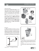
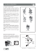
Brake lining and block differ in that
it takes two brake blocks to line one
shoe while a single brake lining
segment is all that is required to do
the same job. Block is generally 3/4"
thick and used on class 8 vehicles
while lining is 1/2" thick and
generally used on smaller vehicles.
While it is recommended that a
matching set of lining be used on
each wheel, under some conditions
a combination of different lining
materials may be desirable. If a
brake system is marginal, for
example, a full step up to a higher
grade lining may give an excessively
large capacity. In this event using a
combination of blocks should be
considered.
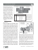
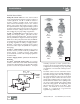
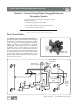
Air Disc Brake
Cut-away View
Lever
Rotor
Eccentric
Bearing
Inner
Brake Pad
Outer
Brake Pad
Actuating
Beam
Actuator
Rod
Supply Port
Brake Block
Brake Lining
FRICTION CODE CHART
Letter Numerical Range
D over 0.150, but less than 0.250
E 0.250 to 0.350
F 0.351 to 0.450
G 0.451 to 0.550
H Over 0.550
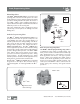
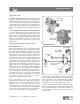
Air Disc Brakes
Bendix air disc brakes are a “floating caliper” design
for use as a foundation brake on all axles of heavy
commercial vehicles and trailers. In terms of
performance and ease of service, Bendix air disc brakes
compared favorably to traditional S-Cam brakes. They
are available in models with or without a combination
spring brake chamber. Optional wear sensors and wear
diagnostic equipment are available on some models.
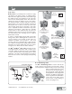
Bendix air disc brakes convert air pressure into braking
force. When the foot brake is applied, air from the
vehicle brake system enters the service brake chamber
through the supply port, applying pressure to the
diaphragm. The pressure pushes the diaphragm, moving
the pressure plate and pushrod against a cup in the
lever. The lever pivots on an eccentric bearing and
transfers motion to the actuating beam. Moving against
return spring force, the actuating beam moves two
threaded tubes and tappets, which force the inner brake
pad into contact with the brake rotor. Further
movement of the actuating beam forces the caliper,
sliding on two stationary guide pins, away from the
rotor, which pulls the outer brake pad into the rotor.
The clamping action of the brake pads on the rotor
applies braking force to the wheel.
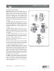
Releasing the foot brake releases pressure in the service
brake chamber. With no pressure in the service brake
chamber, return springs force the air disc brakes into
a neutral, non-braked position. The non-braked
position is mechanically controlled by a brake adjuster
mechanism in the caliper. The caliper contains a brake
adjuster mechanism that turns threaded tubes to set a
gap (running clearance) between the rotor and the
brake pads. When operated manually with the adjuster
shaft, the adjuster mechanism sets the system’s non-
braked position. The adjuster mechanism also operates
automatically, whenever the brakes are activated, to
compensate for rotor and brake pad wear and keep
the running clearance constant.
The rotor-friction couple is carefully designed for
optimal performance and durability. It is recommended
that only approved replacement disc pads or rotors be
used to prevent damage to disc brake components (e.g.
cracked rotors) or premature or uneven pad wear,
which can adversely affect braking performance.
The friction class is
indicated by two letters
(e.g. DF). The first
letter represents the
normal coefficient of
friction, and the second
represents the hot
coefficient of friction.