
Troubleshooting guide


49
www.bendix.com 1-800-AIR-BRAKE (1-800-247-2725)
Leverage
Having reviewed the forces involved in braking a vehicle,
consideration must also be given to how these forces are
developed and directed to do the braking work. Almost
all braking systems make use of one of the oldest
mechanical devices governing the transmission and
modification of force and motion, the lever.
A lever is defined as an inflexible rod or beam capable of
motion about a fixed point called a fulcrum, and it is used
to transmit and modify force and motion.
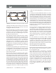
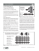
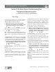
Figure 5 illustrates three simple types of levers; the only
difference in them being the location of the fulcrum in
relation to the applied force and the delivered force. All
shapes and sizes of levers used in a typical brake system
are one of these three types.
The simple law of levers is that the applied force multiplied
by the perpendicular distance between the line of force
and the fulcrum always equals the delivered force multiplied
by the perpendicular distance between the fulcrum and
the line of force. Thus, with a leverage arrangement as
shown in view 5(a), an applied force of 100 pounds two
feet from the fulcrum will give a delivered force of 200
pounds at a point one foot from the fulcrum. With a
leverage arrangement as shown in Figure 5(b), an applied
force of 100 pounds three feet from the fulcrum will lift
300 pounds at a point one foot from the fulcrum.
Note that in both cases the delivered force exceeds the
applied force because the applied force is farther from
the fulcrum than the delivered force. With a leverage
arrangement as shown in Figure 5(c), the delivered force
is the farthest from the fulcrum; therefore, it is less than
the applied force. If the applied force in this case is 300
pounds at a point two feet from the fulcrum, the delivered
force at a point three feet from the fulcrum will be 200
pounds.
The delivered force of any lever is determined by
multiplying the applied force by the distance it is from the
fulcrum and then dividing this answer by the distance the
delivered force is from the fulcrum.
In determining the distance at which any force is acting on
a lever, the true length of the lever arm is the perpendicular
distance from the force to the fulcrum, regardless of the
shape of the lever. The lever arm is always measured at
right angles to the direction of the force.
The product of the force acting on a lever, multiplied by
the distance the force is from the fulcrum, is called the
turning moment, and when this relates to a shaft, it is
called torque. The turning moment or torque is usually
expressed in inch-pounds, foot-pounds, foot-tons, etc.,
depending upon whether the force is measured in pounds
or tons and whether the distance is measured in inches or
feet. As an example – a force of 100 pounds acting on a
lever arm five inches long would result in a turning moment
or torque of 500 inch pounds.
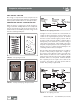
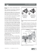
The most easily recognized lever in an air brake system is
the slack adjuster. The length of the lever arm of a slack
adjuster is always the perpendicular distance between the
center line of the brake camshaft opening and the center
line of the clevis pin.
Another form of lever – not always recognized – is the
brake cam. All brake cams are levers and are used to
transmit and modify the torque and turning motion of the
brake camshaft in such a way that the brake shoes are
spread and forced against the brake drum, not only in the
proper direction but also with the proper force. Spreading
the shoes in the proper direction, of course, depends on
the proper location of the cam in respect to the location
of the brake shoes. The transmission of the proper force
is partially determined by the effective lever length of the
cam. If the effective lever length of the cam is too long or
too short, the brake shoe force will be correspondingly
too little or too much.
It is also important that the effective lever length of the
cam remains constant as the lining wears and the shoes
have to be spread further; otherwise, the brake
performance would vary as the lining wears.
FIGURE 5 - Leverage
5(a)
5(b)
5(c)
Leverage