
Troubleshooting guide


54
www.bendix.com 1-800-AIR-BRAKE (1-800-247-2725)
The Fundamentals of
Compressed Air Brakes
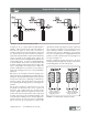
Compressor, Reservoir and Brake Valve
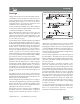
In an air brake system, the compressor supplies the
compressed air for brake operation by taking free air and
compressing it to 100-120 P.S.I. (Maximum pressure in an
air brake system is generally 150 P.S.I.)
The compressed air passes from the compressor into the
reservoir and the air brake system where it (and its energy)
are stored until needed by the driver for a brake
application.
Service Brake System
When the brake valve is operated by the driver, air flows
to the chambers where its energy is transformed into the
mechanical force and motion necessary to apply the brakes.
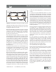
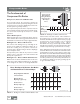
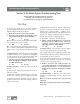
Braking Forces - Effect of Air Pressure
This control of the braking force by controlling the air
pressure in the chambers is illustrated in Figure 14. It
shows the resulting forces in pounds of various air
pressures with a chamber having an effective diaphragm
area of 24 square inches.
The important point is that the air pressure in a brake
chamber can be controlled so the brake chamber will
develop the required force.
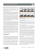
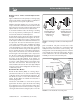
Braking Forces - Effect of Brake Chamber Size
Different sizes of vehicles and different axles of the same
vehicle may require different braking forces, depending
on the weight of the vehicle or the weight distribution
between axles of the same vehicle. These variations in
the braking force are design variations because the
maximum and minimum force required must be properly
provided before good performance can be obtained
throughout the entire braking range. [Note:
Rotochambers are larger, heavier style of brake chamber
typically used on heavier, off-road equipment where their
constant output and longer push-rod stroke is useful.]
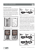
Figure 15 illustrates the developed force in pounds of each
of several different sizes of brake and rotochambers when
supplied with air pressure at 60 pounds per square inch.
The effective area of the different brake chambers generally
varies from six square inches to 36 square inches and their
developed force at 60 pounds air pressure generally varies
from 360 pounds to 2,160 pounds. This permits the choice
of a chamber size suitable for properly operating any size
or type of foundation brake.
FIGURE 15 - Braking Forces-Effect of Brake Chamber Size
Clamp Ring Brake Chamber 6 9 12 16 20 24 30 36 50*
or Rotochamber
Effective Area of 6 9 12 16 20 24 30 36 50
Diaphragm (square in.)
Pounds of Force 180 270 360 480 600 720 900 1090 1500
Developed @ 30 psi
Pounds of Force 360 540 720 960 1200 1440 1800 2160 3000
Developed @ 60 psi
Force Developed by Various Size Brake
and Rotochambers at 30 and 60 psi.
FIGURE 14 - Braking Forces-Effect of Air Pressure
Air Pressure 5 10 20 30 40 60 80 100
(PSI)
Developed 120 240 480 720 960 1440 1920 2400
Force
(PSI)
Typical 'Type-24'
Brake Chamber
Having An Effective
Diaphragm Area
Of 24 Square
Inches.
Compressed Air Brakes
* Rotochamber only