
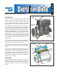
Technical data


5
IMPORTANT NOTE
Replacement air governors must have a minimum
cut-in pressure of 105 psi. The cut-in pressure is the
lowest system pressure registered in the gauges before
the compressor resumes compressing air.
Compressors with no signal line to the unloader port
should have a vent installed in the port rather than a
plug.
SERVICE TESTS: GENERAL
The following compressor operating and leakage tests
need not be performed on a regular basis. These tests
should be performed when it is suspected that leakage is
substantially affecting compressor buildup performance,
or when it is suspected that the compressor is “cycling”
between the load and unloaded modes due to unloader
plunger leakage.
IN SERVICE OPERATING TESTS
Compressor Performance: Build-up Test
This test is performed with the vehicle parked and the
engine operating at maximum recommended governed
speed. Fully charge the air system to governor cut out (air
dryer purges). Pump the service brake pedal to lower the
system air pressure below 80 psi using the dash gauges.
As the air pressure builds back up, time from when the
dash air pressure gauge passes 85 to the time it passes
100 psi. The time should not exceed 40 seconds. If the
vehicle exceeds 40 seconds, test for (and fix) any air leaks
and then re-test the compressor performance. If the vehicle
does not pass the test the second time, use the Advanced
Troubleshooting Guide for Air Brake Compressors, starting
on page 11 of this document to assist your investigation
of the cause(s).
Note: All new vehicles are certified using the FMVSS
121 test (paragraph S5.1.1) by the vehicle manufacturer,
however the above test is a useful guide for in-service
vehicles.
Optional Comparative Performance Check
It may be useful to also conduct the above test with the
engine running at high idle (instead of maximum governed
speed), and record the time taken to raise the system
pressure a selected range (for example, from 90 to 120
psi, or from 100 to 120 psi, etc.) and record it in the
vehicle’s maintenance files. Subsequent build-up times
throughout the vehicle’s service life can then be compared
to the first one recorded. (Note: the 40 second guide in
the test above does not apply to this build-up time.) If the
performance degrades significantly over time, you may
use the Advanced Troubleshooting Guide for Air Brake
Compressors, starting on page 11 of this document, to
assist your investigation of the cause(s).
Note: When comparing build-up times, be sure to make
an allowance for any air system modifications which would
cause longer times, such as adding air components or
reservoirs. Always check for air system leakage.
LEAKAGE TESTS
See the standard Air Brake System and Accessory Leakage
test on Page 24 (Test 2).
Note: Leakage in the air supply system (components
before the supply reservoir - such as the governor, air dryer,
reservoir drain cocks, safety valve and check valves) will
not be registered on the vehicle dash gauges and must
be tested separately. Refer to the various maintenance
manuals for individual component leakage tests and the
Bendix “Test and Checklist” published in the Air Brake
System Handbook (BW5057) and on the back of the Dual
Circuit Brake System Troubleshooting card (BW1396).
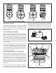
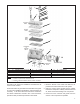
Cylinder Head
Check for cylinder head gasket air leakage.
1. With the engine running, lower air system pressure to
60 psi and apply a soap solution around the cylinder
head. Check the gasket between the cylinder head
and valve plate assembly and the reed valve/gasket
between the valve plate assembly and cylinder block
for air leakage.
2. No leakage is permitted. If leakage is detected replace
the compressor or repair the cylinder head using a
genuine Bendix maintenance kit available from an
authorized Bendix parts outlets.
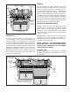
Inlet, Discharge & Unloader
In order to test the inlet and discharge valves and the
unloader piston, it is necessary to have shop air pressure
and an assortment of fittings. A soap solution is also
required.
1. With the engine shut off, drain ALL air pressure from
the vehicle.
2. Disconnect the inlet and discharge lines and remove
the governor or its line or adapter fitting.
3. Apply 120-130 psi shop air pressure to the unloader
port and soap the inlet port. Leakage at the inlet port
should not exceed 50 sccm.
4. Apply 120-130 psi shop air pressure to the discharge
port and then apply and release air pressure to the inlet
port. Soap the inlet port and note that leakage at the
inlet port does not exceed 20 sccm.
If excessive leakage is noted in tests 3 or 4, replace or
repair the compressor using genuine Bendix replacements
or maintenance kits available from any authorized Bendix
parts outlet.