
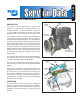
Technical data


6
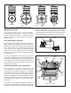
While it is possible to test for inlet, discharge, and unloader
piston leakage, it may not be practical to do so. Inlet and
discharge valve leakage can generally be detected by
longer compressor buildup and recovery times. Compare
current compressor buildup times with the last several
recorded times. Make certain to test for air system leakage,
as described above, before making a determination that
compressor performance has been lost.
Unloader leakage is exhibited by excessive compressor
cycling between the loaded and unloaded condition.
1. With service and supply system leakage below the
maximum allowable limits and the vehicle parked,
bring system pressure to governor cutout and allow
the engine to idle.
2. The compressor should remain unloaded for a minimum
of 5-10 minutes. If compressor cycling occurs more
frequently and service and supply system leakage is
within tolerance (including any leakage that may be
present at the air dryer exhaust) replace or repair the
compressor unloader system using a genuine Bendix
maintenance kit available from authorized Bendix parts
outlets.
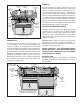
COMPRESSOR REMOVAL & DISASSEMBLY
GENERAL
The following disassembly and assembly procedure is
presented for reference purposes and presupposes that
a rebuild or repair of the compressor is being undertaken.
Several maintenance kits are available and the instructions
provided with these parts and kits should be followed in
lieu of the instructions presented here.
MAINTENANCE KITS & SERVICE PARTS
Cylinder Head Gasket Kit ........................................5014472
Unloader Kit ............................................................. 5014473
Governor Adapter Kit ...............................................
5008561
Compressor Seal Kit (crankcase) ............................ 5008559
Cat MD Seal Kit .......................................................5012367
Cat HD Seal Kit ....................................................... 5012369
Series 60 Seal Kit ....................................................5012371
ST-4 Discharge Safety Valve (7/8"-14 thrd.) .............. 801116
ST-4 Discharge Safety Valve (M16-1.5 thrd.) ............800534
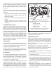
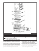
All components shown in Figure 10 with a key number are
available in kits and/or as individual service parts.
IMPORTANT! PLEASE READ AND FOLLOW
THESE INSTRUCTIONS TO AVOID
PERSONAL INJURY OR DEATH:
When working on or around a vehicle, the following
general precautions should be observed
at all times:
1. Park the vehicle on a level surface, apply the parking
brakes, and always block the wheels. Always wear
safety glasses. Where specifically directed, the
parking brakes may have to be released, and/or
spring brakes caged, and this will require that the
vehicle be prevented from moving by other means
for the duration of these tests/procedures.
2. Stop the engine and remove ignition key when
working under or around the vehicle. When working
in the engine compartment, the engine should be
shut off and the ignition key should be removed.
Where circumstances require that the engine be in
operation, EXTREME CAUTION should be used to
prevent personal injury resulting from contact with
moving, rotating, leaking, heated or electrically
charged components.
3. Do not attempt to install, remove, disassemble
or assemble a component until you have read
and thoroughly understand the recommended
procedures. Use only the proper tools and observe
all precautions pertaining to use of those tools.
4. If the work is being performed on the vehicle’s
air brake system, or any auxiliary pressurized air
systems, make certain to drain the air pressure from
all reservoirs before beginning ANY work on the
vehicle. If the vehicle is equipped with an AD-IS
®
air
dryer system or a dryer reservoir module, be sure
to drain the purge reservoir.
5. Following the vehicle manufacturer’s recommended
procedures, deactivate the electrical system in a
manner that safely removes all electrical power from
the vehicle.
6. Never exceed manufacturer ’s recommended
pressures.
7. Never connect or disconnect a hose or line containing
pressure; it may whip. Never remove a component
or plug unless you are certain all system pressure
has been depleted.
8. Use only genuine Bendix
®
replacement parts,
components and kits. Replacement hardware,
tubing, hose, fittings, etc. must be of equivalent
size, type and strength as original equipment and
be designed specifically for such applications and
systems.
9. Components with stripped threads or damaged
parts should be replaced rather than repaired. Do
not attempt repairs requiring machining or welding
unless specifically stated and approved by the
vehicle and component manufacturer.
10. Prior to returning the vehicle to service, make certain
all components and systems are restored to their
proper operating condition.
11. For vehicles with Antilock Traction Control (ATC),
the ATC function must be disabled (ATC indicator
lamp should be ON) prior to performing any vehicle
maintenance where one or more wheels on a drive
axle are lifted off the ground and moving.
REMOVAL
In many instances it may not be necessary to remove the
compressor from the vehicle when installing the various
maintenance kits and service parts. The maintenance