
Technical data

7
technician must assess the installation and determine the
correct course of action.
These instructions are general and are intended to be a guide.
In some cases additional preparations and precautions are
necessary. In all cases follow the instructions contained in
the vehicle maintenance manual in lieu of the instructions,
precautions and procedures presented in this manual.
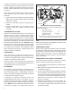
1. Block the wheels of the vehicle and drain the air
pressure from all the reservoirs in the system.
2. Drain the engine cooling system and the cylinder
head of the compressor. Identify and disconnect all
air, water and oil lines leading to the compressor.
3. Remove as much road dirt and grease from the
exterior of the compressor as possible.
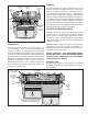
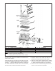
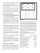
FIGURE 9 - BA-922
®
COMPRESSOR EXPLODED VIEW OF SERVICEABLE PARTS
Item Qty. Description Item Qty. Description Item Qty Description
1 2 Unloader Cover Cap Screw 6
1
1 O-Ring 11 2
2
Head Gasket
2
1
1 Unloader Cover 7
1
1 O-Ring 12 1
2
Inlet Reed Valve/Gasket
3
1
1 Unloader Cap Gasket 8
1
1 Unloader Piston 13 1
3
O-Ring
4
1
1 Unloader Balance Piston 9
1
1 O-Ring 14 1
3
Bottom Cover Gasket
5
1
1 Spring 10 1 ST-4
™
Safety Valve
Notes: 1. Contained in Unloader Kit 5014473
2. Contained in Cylinder Head Gasket Kit 5014472
3. Contained in Seal Kits 5008559, 5008561, 5008557 & 5008558
Crankcase
Cover
Crankcase
&
Cylinder
Block
Cylinder
Head
Cooling
Plate
Valve
Plate
Assy.
4
5
3
6
7
8
9
2
11
11
12
13
14
10
1
End Cover