
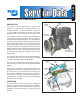
Technical data

8
4. Remove the discharge and inlet fittings, if applicable, and
note their position on the compressor to aid in reassembly.
Note: If a cylinder head maintenance kit is being installed,
stop here and proceed to PREPARATION FOR
DISASSEMBLY. If replacing the compressor
continue.
5. Remove any supporting bracketing attached to the
compressor and note their positions on the compressor
to aid in reassembly.
6. Remove the flange mounting bolts and remove the
compressor from the vehicle.
7. Inspect gear and associated drive parts for visible wear or
damage. Since these parts are precision fitted, they must
be replaced if they are worn or damaged. If replacing
the compressor or replacing the drive gear, remove the
drive gear from the compressor crankshaft using a gear
puller.
8. If the compressor is being replaced stop here and
proceed to "Installing The Compressor" at the end of
the assembly procedure.
PREPARATION FOR DISASSEMBLY
Remove the balance of road dirt and grease from the
exterior of the compressor with a cleaning solvent. Mark
the rear end cover or end cover adapter in relation to
the crankcase. It is recommended but not specifically
necessary to mark the relationships of the cylinder head,
cooling plate, valve plate assembly, crankcase and cylinder
block assembly.
A convenient method to indicate the above relationships
is to use a metal scribe to mark the parts with numbers or
lines. Do not use marking methods such as chalk that can
be wiped off or obliterated during rebuilding.
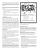
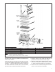
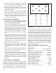
Prior to disassembly make certain that the appropriate kits
and/or replacement parts are available. Refer to Figure 9
during the entire disassembly and assembly procedure.
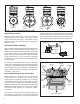
CYLINDER HEAD
1. Remove the discharge safety valve (10) from the
cylinder head.
2. To restrain the spring force exerted by balance piston
spring (5), hold the unloader cover (2) in place while
removing the two unloader cover cap screws (1).
Carefully release the hold on the unloader cover until
the spring force is relaxed, then remove the unloader
cover (2).
3. Remove the unloader cover gasket (3).
4. Remove the balance piston (4) and its spring (5) from
the cylinder head.
5. Remove the six hex head bolts and washers from the
cylinder head.
6. Remove the two bolts located in the center of the head.
Gently tap the head, cooling plate and valve plate
assembly with a soft mallet to break the gasket seal.
Lift the cylinder head with cooling plate and valve plate
assembly off the cylinder block.
7. Remove the metal reed valve/gasket (12).
8. Gently tap the head, cooling plate and valve plate
assembly with a soft mallet to break the gasket seals.
Then separate the cylinder head from the cooling plate
and valve plate assembly and remove the gasket (11)
between them.
9. Turn the aluminum cylinder head over to expose the
interior portion of the head. Push the unloader piston
(7) along with its o-rings (6, 8 & 9) out of the cylinder
head.
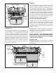
CRANKCASE COVER
1. Remove the four crankcase cover cap screws securing
the crankcase cover to the crankcase. Using a soft
mallet, gently tap the crankcase cover to break the
gasket seal. Remove the crankcase cover gasket
(14).
REAR END COVER OR END COVER ADAPTER
1. Remove the four end cover cap screws that secure
the rear end cover or end cover adapter to the
crankcase.
2. Remove the rear end cover or end cover adapter from
the crankcase. Remove the o-ring seal (13) from the
end cover.
CLEANING OF PARTS
GENERAL
All parts should be cleaned in a good commercial grade of
solvent and dried prior to inspection.
CYLINDER HEAD
1. Carefully remove all gasket material adhering to the
aluminum cylinder head, steel valve plate assembly
and cast iron cylinder block. Make certain not to deeply
scratch or mar the gasket surfaces. Pay particular
attention to the gasket surfaces of the aluminum
head.
2. Remove carbon deposits from the discharge and inlet
cavities of the cylinder head and valve plate assembly.
They must be open and clear in both assemblies. Make
certain not to damage the aluminum head.
3. Remove rust and scale from the cooling cavities and
passages in the head and valve plate assembly and
use shop air to clear debris from the passages.
4. Check the threads in all cylinder head ports for galling.
Minor chasing is permitted.
5. Make certain the unloader vent passage under the
unloader cover (2) in the head is open and free of
debris.