
Technical data


9
INSPECTION OF PARTS
CYLINDER HEAD & VALVE PLATE
1. Carefully inspect the cylinder head gasket surfaces for
deep gouges and nicks. If detected, the compressor
must be replaced.
2. Carefully inspect the valve plate assembly gasket
surfaces for deep gouges and nicks. Pay particular
attention to the metal gasket surface. A metal gasket
(12) is used between the valve plate assembly and
cylinder block. This surface must be smooth and
free of all but the most minor scratching. If excessive
marring or gouging is detected, the compressor must
be replaced.
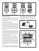
3. Inspect the cylinder head for cracks or damage. With the
cylinder head and head gasket secured to the valve plate
assembly, apply shop air pressure to one of the coolant
ports with all others plugged, and check for leakage by
applying a soap solution to the exterior of the head. If
leakage is detected in the cylinder head casting, replace the
compressor.
END COVER OR END COVER ADAPTER
Check for cracks and external damage. Check the
crankshaft main bearing surface in the end cover or end
cover adapter, check for excessive wear and flat spots and
replace the end cover if necessary. Check for galling of
the oil port threads and replace the end cover or end cover
adapter if necessary. Minor thread chasing is permitted but
do not “recut” the threads if they are badly damaged.
CYLINDER BLOCK
1. Check the cylinder head gasket surface on the cylinder
block for nicks, gouges, and marring. A metal gasket
is used to seal the cylinder head to the cylinder block.
This surface must be smooth and free of all but the most
minor scratching. If excessive marring or gouging is
detected, the compressor must be replaced.
DISCHARGE LINE
1. Inspect the discharge line for kinks, damage, or carbon
deposits. Replace as necessary. See the advanced
troubleshooting guide for more information.
ASSEMBLY
General Note: All torques specified in this manual are
assembly torques and typically can be expected to fall off
after assembly is accomplished. Do not re-torque after
initial assembly torques fall unless instructed otherwise.
A compiled listing of torque specifications is presented on
page 11 of this manual.
INCH POUNDS TO FOOT POUNDS
To convert inch pounds to foot pounds of torque, divide
inch pounds by 12.
Example:
12 Inch Pounds
= 1 Foot Pound
12
FOOT POUNDS TO INCH POUNDS
To convert foot pounds to inch pounds of torque, multiply
foot pounds by 12.
Example: 1 Foot Pound
x 12 = 12 Inch Pounds
CRANKCASE COVER
1. Position the crankcase cover gasket (14) on either the
crankcase or crankcase cover and install the crankcase
cover on the crankcase using the four cap screws.
"Snug" the four cap screws then torque to 62-71 inch
pounds (7-8 Nm) using a crossing pattern.
CRANKCASE END COVER OR ADAPTER
1. Install the end cover o-ring (13) on the crankcase end
cover.
2. Orient the crankcase end cover or end cover adapter to
the crankcase using the reference marks made during
disassembly. Carefully install the end cover or end
cover adapter in the crankcase making certain not to
damage the crankshaft bearing surface in it.
3. Install the four end cover screws or studs. "Snug" the
screws then tighten to 195 to 213 inch pounds (22-24
Nm) using a crossing pattern.
CYLINDER HEAD
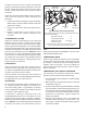
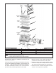
1. Note the position of the protruding alignment pins on the
cylinder block. Install the metal inlet reed valve/gasket
(12) over the alignment pins on the cylinder block.
2. Position the valve plate assembly on the cylinder block
so that the alignment pins in the cylinder block fit into
the corresponding holes in the valve plate assembly.
3. Position and install one of the metal gaskets (11) over
the alignment bushings protruding from the valve plate
assembly. When properly installed, the outline of the
gasket matches the outline of the valve plate.
4. Install the cooling plate over the alignment bushings
protruding from the valve plate assembly. Again, when
properly installed, the outline of the cooling plate
matches the outline of the valve plate.
5. Position and install the other metal gasket (11) over the
alignment bushings protruding from the cooling plate
assembly. The outline of the gasket matches the outline
of the cooling plate.
6. Position and install the cylinder head over the alignment
bushings protruding from the cooling plate.
Note: The alignment bushings will only fit into
two of the six cylinder head bolt holes.
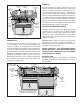
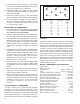
7. Install the two center bolts and six hex head cylinder
head bolts and washers and snug them, then tighten
evenly to a torque of 265 to 292 inch pounds (30-33
Nm) using the pattern shown in Figure 9.
8. Install the unloader piston (7) with its pre-installed
o-rings (6, 8, 9) in the cylinder head making certain not
to damage them in the process.