TRT800H P/N 800ATC-H-(0XX)-(0XX) P/N 800ATC-H-(1XX)-(1XX) P/N 800ATC-H-(2XX)-(1XX) ATC Transponder Mode A, A-C, S Installation and Operation Dokument-Nr.: 03.2121.010.71e Revision: 1.03 Date: 06.07.2007 Filser Electronic GmbH • Gewerbestraße 2 • 86875 Waal phone: 08246 / 96 99-0 • fax: 08246 / 10 49 • web: www.filser.
TRT800H Installation and Operation List of Changes Revision Date Description of Change 1.00 29.01.2007 initial version 1.01 16.02.2007 description SUPP_I/O mounting of rotary knobs, AC-Code table, ground switch description 1.02 27.03.2007 Entering AA-Code, 8 AA-Codes can be stored 1.03 06.07.2007 Description Address Adapter Responsibility for transponder data List of Service Bulletins (SB) Service Bulletins have to be inserted into this manual and to be enlisted in the following table. SB No 2 Rev.
TRT800H Installation and Operation Contents 1 GENERAL.........................................................................................5 1.1 Symbols ......................................................................................5 1.2 Customer Support.......................................................................5 1.3 Survey of Variants.......................................................................6 1.4 Introduction .............................................................
TRT800H Installation and Operation 6 OPERATION................................................................................... 27 6.1 ON/OFF .................................................................................... 27 6.2 FID – Flight ID........................................................................... 27 6.3 Transponder Mode Selection .................................................... 28 6.4 Squawk Setting .........................................................................
TRT800H Installation and Operation 1 GENERAL 1.1 Symbols Instructions whose non-observance can cause radiation damage to the human body or ignition of combustible materials. Instructions whose non-observance can cause damage to the device or other parts of the equipment. Supplementary information. 1.2 Customer Support For fastest handling of reshipments please use the reshipment form available from our homepage www.filser.de. Any suggestions for improvement of our manuals are welcome.
TRT800H Installation and Operation 1.3 Survey of Variants Part Number Description P/N 800ATC-H-(0XX)-(0XX) prior to SW3.
TRT800H Installation and Operation 1.4 Introduction This manual contains information about the physical, mechanical and electrical characteristics and about installation and operation of the TRT800H Mode S Transponder. Please care for the ICAO 24-Bit Aircraft Address before installation. Ask your national aviation authority. 1.
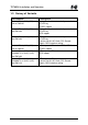
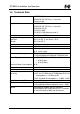
TRT800H Installation and Operation 1.6 Technical Data Compliance Applicable Documents Mounting Temperature Ranges Operation Storage Altitude Range Vibration Shock CS-ETSO-2C112a EUROCAE ED-73B Class 1 Level 2es EASA.21O.045 CS-ETSO-2C112a EUROCAE ED-73B Class 1 Level 2es EUROCAE ED-26 RTCA DO-160D RTCA DO-178B Software-Level D Panel cut-out Ø 57 mm -20 °C to +55 °C; for 30 min +70°C -55 °C to +85 °C 15,000 ft DO160D, Cat.
TRT800H Installation and Operation Mode S Elementary Surveillance 24-bit Aircraft Address aircraft address FID Flight ID: Flight Plan call sign or aircraft registration marking Capability Report Reports the available data and means by which the transponder can report. Pressure Altitude up to 35,000 ft in 100 ft increments Flight Status in-flight / on-ground Mode S Enhanced Surveillance Level 2es Comm-A / Comm-B: 56/112-Bit-Messages SI/II code-capability 1.
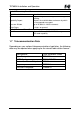
TRT800H Installation and Operation 1.8 Environmental Conditions Characteristic DO–160D Temperature / Altitude Low ground survival temperature Low operating temperature High ground survival Temperature High Short-time Operating Temperature High Operating Temperature In-Flight Loss of Cooling Altitude Section Cat. 4.0 4.5.1 4.5.1 4.5.2 C1 Condition – 55°C – 20°C + 85°C 4.5.2 + 70°C 4.5.3 4.5.4 4.6.1 Z C1 Temperature Variation 5.
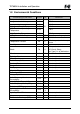
TRT800H Installation and Operation 1.9 Scope of Delivery Filser Part Number TRT800H TRT800EM MA8K1101 (4 pieces) 03.2121.010.71e Description Transponder TRT800H AC Address Adapter EM800 with cables through-hole screw for panels up to 3 mm thickness Manual “Installation and Operation” EASA Form 1 1.
TRT800H Installation and Operation 2 INSTALLATION 2.1 Note The following suggestions should be considered before installing. The installer will supply wiring. For diagrams refer to chapter 4 WIRING. Transponder, AC address adaptor, all cables and antennas should be installed as per “FAA Advisory Circular AC43.13-2A Methods and Guidelines” and the appropriate manufacturer’s instructions. 2.2 Unpacking and Inspecting of the Equipment Carefully unpack the equipment and inspect for transport damages.
TRT800H Installation and Operation 2.3 Mounting • For mounting details/drawing refer to chapter 5 DRAWINGS. • In cooperation with a maintenance shop, location and kind of the installation are specified. The maintenance shop can supply all cables. Suitable sets of cables are available from Filser Electronic GmbH. • Select a position away from heat sources. Care for adequate convection cooling. • Leave sufficient space for the installation of cables and connectors.
TRT800H Installation and Operation 2.4 Equipment Connections 2.4.1 Electrical Connections The 15 pin D-SUB connector includes all electrical connections, except the antenna line, which is connected by a TNC jack. Use only an AC Address Adaptor TRT800EM or ZTRT800EMSS for they include an EEPROM with the memorized ICAO Aircraft code. The TRT800 has to be protected by an external slow-blow fuse of 2 amperes. 2.4.
TRT800H Installation and Operation 2.4.4 Mutual Suppression Other equipment on board (e. g. DME or TACAN) may transmit in the same frequency band as the transponder. Mutual suppression is a synchronous pulse that is sent to the other equipment to suppress transmission of a competing transmitter for the duration of the pulse train transmission. The transponder transmission may be suppressed by an external source and vice versa.
TRT800H Installation and Operation • Keep away three feet from the ADF sense antenna or any other communication antenna and six feet from the DME antenna. • Pursue mounting in vertical position under the belly 2.5.3 Antenna Wiring • • • • Refer to 1.10 Accessories for suitable antenna cables. Keep wiring as short as possible. Avoid sharp bends. Avoid cable running near RF generating sources (generators, trim motors, ignition coil or battery charger).
TRT800H Installation and Operation 3 SETTINGS 3.1 Overview The TRT800 has the contingency of storing the following information (For model differences refer to 1.3 Survey of Variants.): • error logging • one entry/eight entries for o ICAO 24-Bit Aircraft Address (AA) o Aircraft Category identification code (AC) o Flight Identification (FID) o ground switch availability o interface configuration AA, AC and FID are stored in a memory device inside the housing of the D-SUB connector (included in delivery).
TRT800H Installation and Operation 3.1.3 Aircraft Category Identification Code (AC) Code 11 12 19 Description vehicle emergency vehicle glider Code 1C 1E 21 1A 1B balloon & airship paraglider 27 Description ultra light drone light aircraft, motor glider, < 7031 kg (15.500 lbs) helicopter 3.1.
TRT800H Installation and Operation 3.1.6 RS232 Interface For model differences refer to 1.3 Survey of Variants. With the additionally available address adaptor ZTRT800EMSS the RS232 interface can be connected to a datalink processor (COMM-A/B) or to a GPS system. • COMM-A/B-usage: o COMM-A e. g. to receive the Traffic Information Service (TIS) o COMM-B to transmit a ground- or an air-initiated message or to transmit an addressed air-initiated message to a specified ground station.
TRT800H Installation and Operation 3.2 Configuration Programming of the ICAOA 24-bit Aircraft Address and of the Aircraft Category shall be executed by qualified personnel only! A wrong Aircraft Address or Flight ID may cause serious problems with ACAS or ATC systems! Pilot and owner are responsible for correctly set transponder data, which shall be checked prior to every flight.
TRT800H Installation and Operation List of Functions Counter Function 1..4 just display AA/AC/FID data o display automatically returns to STBY 5..19 change FID only (AA/AC input locked) o turn ..X. to set cursor (“^”) o turn .X.. to select characters o press MOD to save and to return to STBY 20 test mode (refer to chapter 3.3) 40 display error logging o press MOD to return to STBY 47 change ICAO-Address/Aircraft Category/FID o turn ..X. to set cursor (“^”) o turn .X..
TRT800H Installation and Operation 3.3 Test Mode Refer to 3.2 for entering the test mode. In this mode all transponder functions are still active but more details are shown on the display.
TRT800H Installation and Operation P A E T mmmm ft FLerr ADS-B position input init COM-B event driven squitter TRA (BDS 07) flight level faulty altitude value A-C ACS STBY 4444 F G stand-by squawk value in-flight on-ground out of -1000 .. 35000 ft, C mode deactivated operating mode state of ground switch (if connected) Leave test mode: • press MOD (repeatedly) until “STBY” is displayed • press FID once Dokument-Nr.: 03.2121.010.71e / Revision: 1.
TRT800H Installation and Operation 4 WIRING 4.1 Conductor Cross-Section Power, GND: AWG20 (0,62 mm²) Signals: AWG22 (0,38 mm²) The conductors must be approved for aircraft use. 4.
TRT800H Installation and Operation 4.3 TRT800EMSS – Address Adaptor with RS232 **) *) Ground Switch/ If a ground switch is connected, in “on-ground“ state pin 15 must be connected to „Power GND“, FLY_GND otherwise leave Pin 15 open. **) LIGHT Notice chapter 2.4.3 Background Illumination! Dokument-Nr.: 03.2121.010.71e / Revision: 1.
TRT800H Installation and Operation 5 DRAWINGS Equipment Dimensions 65 mm Power/RS232 Static Air Antenna 65 mm TRT800 TRT800H Ø 57 mm 170 mm 15 mm Connector Area 20mm Panel Cut-out ≈ 80 mm 47,0 mm 57,5 mm 4 x Ø 6,5 mm 47,0 mm 26 Dokument-Nr.: 03.2121.010.71e / Revision: 1.
TRT800H Installation and Operation 6 OPERATION 6.1 ON/OFF • power on: press approx. 0.5 s • power off: press approx 3 s display after power on: Gerätename Software-Version Firmware-Version FPGA-Vers. 21 From SW 3.10: If more than one aircraft address/FID exist, select the correct entry with the rotary knob .X.. and confirm with MODE. 6.2 FID – Flight ID • Press MOD (repeatedly) to enter “STBY” mode. • Press and hold FID while a counter is shown beside the active squawk.
TRT800H Installation and Operation • Release FID at the corresponding value for following functions: 1..4 just display AA/AC/FID data o display automatically returns to STBY 5..19 change FID only (AA/AC input locked) o turn ..X. to set cursor (“^”) o turn .X.. to select characters o press MOD to save and to return to STBY 6.3 Transponder Mode Selection Press MOD (repeatedly) to select from the following modes: • ACS Standard condition; transponder responds to mode A, C and S interrogations.
TRT800H Installation and Operation 6.5 VFR – Visual Flight Rules For model variants refer to 1.3 Survey of Variants. Equipment from SW3.00 The transponder features a user-defined squawk code for VFR-flight (factory setting: 7000): • Activate VFR mode and VFR squawk: Press VFR in normal mode. • Return to normal mode: Use VFR key or any rotary knob (VFR squawk remains active). • Save active squawk as VFR squawk: Keep VFR pressed until “S” is displayed (3 s); after releasing the key, VFR mode is activated.
TRT800H Installation and Operation 6.6 ID – Special Position Identification (SPI) Press ID to activate transmission of the special position identification pulse with every reply within 18 seconds; “IDT” appears on the display. 6.7 Error Codes For possibly displayed errors refer to 6.8 Display. 6.8 Display Line 1 2 3 4 Display R SE PLL TRX/ANT/DC IDT BAT FL0100/FLerr ACS/ STBY G/F Ex.
TRT800H Installation and Operation 6.9 Controls For model variants refer to 1.3 Survey of Variants. ON/OFF VFR ON press for 0,5 s OFF press for 3 s activate VFR (also deactivate; model dependent) (select VFRD/VFRW; model dependent) store active squawk as VFR/VFRW squawk (press for 3 s) swap active and stand-by squawk IDENT activate SPI pulse MODE select mode ACS, A-S or stand-by FID select FID setting (in stand-by mode; press for 5 s) X…/.X../..X./…X set according squawk digit ..X.