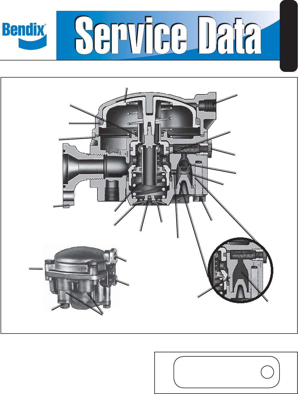
SD-03-1151 Bendix® RE-6™ and RE-6NC™ Relay Valves RELAY PISTON SERVICE PORT EMERGENCY PISTON O-RING INLET AND EXHAUST VALVE SEALING RING EMERGENCY SUPPLY PORT RE-6™ Valve CHECK VALVE SPRING MOUNTING FLANGE SPRING DIAPHRAGM ™ RE-6 & RE-6NC Valves CAP SCREW WASHER SCREW CHECK VALVE DELIVERY PASSAGE ™ RESERVOIR PORT (2) SERVICE PORT EMERGENCY PORT RE-6NC VALVE ID TAG ATTACHED SEE (FIGURE 2) ™ DELIVERY PORTS (4) CHECK VALVE DELIVERY PASSAGE NOT PRESENT RE-6NC™ Valve CHECK VALVE NOT PRESENT
Service Brake Chamber Slack Adjuster Trailer Gladhand CONTROL LINE R-12P™ Valve FRONT Single Check Valve Bulkhead Reservoir RE-6™ Valve Drain Valve SV-4™ Valve SUPPLY LINE RE-6™ RELAY VALVE DOLLY SYSTEM CONFIGURATION Service Brake Chamber Slack Adjuster Trailer Gladhand CONTROL LINE R-12P™ Valve FRONT Single Check Valve Bulkhead Reservoir PR-3™ Valve Single Check Valve SV-4™ Valve Drain Valve SUPPLY LINE RE-6NC™ RELAY VALVE DOLLY SYSTEM CONFIGURATION FIGURE 3 - RE-6™ & RE-6NC™ RELAY
on to the relay portion of the valve. The emergency function of the valve automatically applies full trailer reservoir air pressure to the trailer chambers when the trailer supply pressure falls below a predetermined minimum value. The RE-6™/RE-6NC™ relay emergency valve may be flange or reservoir mounted. Ports are clearly identified for delivery, service, emergency (supply) and reservoir lines.
EMERGENCY SUPPLY 45<>60 PSI RESERVOIR 45<>60 PSI EMERGENCY SUPPLY 60 PSI RESERVOIR 60 PSI 45<>60 PSI CHAMBERS HOLDING CHAMBERS 0 PSI RE-6™ Relay Valve RE-6™ Relay Valve 60 PSI 45<>60 PSI 0 PSI 0 PSI 0 PSI 0 PSI ™ RE-6NC Relay Valve RE-6NC™ Relay Valve FIGURE 5 RE-6™ & RE-6NC™ RELAY VALVES CHARGING HOLD POSITION FIGURE 6 RE-6™ & RE-6NC™ RELAY VALVES CHARGING ABOVE 60 PSI RE-6™ & RE-6NC™ VALVES CHARGING HOLD POSITION allowing drive away.
RE-6™ & RE-6NC™ VALVES SERVICE APPLICATION SERVICE HOLD 5 PSI During normal, service braking operation, the valve serves as a relay valve, synchronizes tractor service (application) EMERGENCY SUPPLY 70 PSI RESERVOIR 70 PSI CHAMBER HOLD 5 PSI NO AIR FLOW FIGURE 9 RE-6™ & RE-6NC™ RELAY VALVES SERVICE HOLD RE-6NC™ Relay Valve FIGURE 7 RE-6NC™ RELAY VALVE CHARGING ABOVE 70 PSI air pressure with trailer service (application) air pressure as the service foot brake valve on the tractor is operated.
RE-6™ & RE-6NC™ VALVES EMERGENCY APPLICATION (Trailer air system charged to normal operating pressure). Venting the emergency supply line to atmosphere will cause the emergency portion of the relay emergency valve to apply full trailer reservoir pressure to the trailer service chambers. If the emergency supply line pressure is reduced to approximately 20 psi, a graduated trailer air chamber application will occur.
8. Use only genuine Bendix® replacement parts, components and kits. Replacement hardware, tubing, hose, fittings, etc. must be of equivalent size, type and strength as original equipment and be designed specifically for such applications and systems. 9. Components with stripped threads or damaged parts should be replaced rather than repaired. Do not attempt repairs requiring machining or welding unless specifically stated and approved by the vehicle and component manufacturer. 10.
7. Remove and discard o-ring(7) from under the crimpedon retaining ring located in the upper portion of the valve body. 8. Turn the valve over, holding the exhaust cover, remove the 3 cap screws(27) from the exhaust cover(22). Remove the spring(20) and set the cap screws and spring aside for the assembly process. 9. Remove and discard the small o-ring(19) from the exhaust cover (located on the check valve post). 10. The RE-6NC™ valve will not have a check valve(17) and spring(18). 11.
O-RING (7) BODY COVER (1) O-RING (8) EMERGENCY PISTON (9) O-RING (2) INLET & EXHAUST VALVE (10) VALVE RETAINER (11) RELAY PISTON (3) INLET EXHAUST VALVE ASSEMBLY SPRING (12) O-RING (13) SEAT (4) O-RING (14) VALVE GUIDE (15) SPRING (5) VALVE RETAINER (16) CHECK VALVE (17) SPRING (18) SEE NOTE 1 SPRING (20) O-RING (19) A CHECK VALVE POST O-RING (21) EXHAUST COVER (22) DIAPHRAGM (23) SEALING RING (6) WASHER (24) SCREW (25) LOCKWASHER (26) CAP SCREW (27) FIGURE 12 EXPLODED VIEW Note 1: The OE
OPERATION Air flow in the normal direction moves the check valve from its seat, and the flow is unobstructed. Flow in the reverse direction is prevented by the seating of the ball or wafer-type disc, which is caused by a drop in up-stream air pressure and assisted by the spring. PREVENTATIVE MAINTENANCE Every six months, 1,800 operating hours or every 50,000 miles inspect all parts. Replace any check valves leaking or showing signs of wear or deterioration. Check for proper operation.
BW1570 © 2007 Bendix Commercial Vehicle Systems LLC. All rights reserved. 7/2007 Printed in U.S.A.