
User's Manual
10
3. After installing the unit, perform the “OPERATION &
LEAKAGE TESTS” for the air valve before placing the
vehicle in service.
DISASSEMBLY
PREPARATION FOR DISASSEMBLY
1. Remove all air fittings and plugs from the valve.
2. Mark the relationship of the valve cover(2) to the body(1)
and, if the valve is equipped with a mounting bracket(41),
mark the relationship of the bracket to the cover and
body(1).
3. Mark the relationship of the electronic controller(39) to
the cover(2).
DISASSEMBLY
The following disassembly and assembly procedure is
presented for reference purposes only. Instructions
packaged with repair and maintenance kits should always
be followed instead of the instructions presented here.
CAUTION: The valve may be lightly clamped in a bench
vise during disassembly, however, over clamping will result
in damage to the valve and result in leakage and/or
malfunction. If a vise is to be used, position the valve so
that the jaws bear on the supply ports on opposing sides of
the valve body.
1. While holding the exhaust cover(4), remove the retaining
ring(3) that secures it to the body(1).
2. Remove the exhaust cover(4) along with both o-rings(5
& 6).
3. Remove the valve spring(7), valve retainer(8), and the
valve assembly(9) from the body(1).
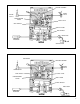
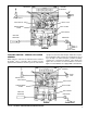
4. Referring to Figure 2, remove and retain the four cap
screws(38) that secure the electronic controller(39) to
the cover(2), then separate and retain the controller(39),
from the cover(2).
5. Remove and retain the two long cap screws(10),
washers(45 and 46) and nuts(43) that secure the cover(2)
to the body(1).
6. Remove and retain the two cap screws and lock
washers(42) that secure the bracket(41) to the cover(2),
then remove and retain the bracket.
7. Remove and retain the two short cap screws(40) that
secure the cover(2) to the body(1).
8. Separate the cover(2) from the body(1), then remove the
sealing ring(35) and o- ring(11).
9. Remove the relay piston(12) and relay piston spring(14)
from the body(1). NOTE: The relay piston spring, item
14 is not used in all valves.
10. Remove the o-ring(13) from the relay piston(12).
11. Remove the retaining ring(15). Then remove check valve
seat(16), with o-rings(20 & 21). Remove o-rings(20 &
21) from the check valve seat.
12. Remove the check valve(17), guide(18), and spring(19).
13. Remove the inlet seat(36) with o-rings(37 & 44), then
remove and discard o-rings(37 & 44) from the inlet
seat(36).
14. Remove the spring(22) then remove and retain the spring
cage(23) from the valve cover(2).
15. Use shop air at the control port to extract the blend
back piston(24) from the valve cover(2). Retain the
piston(24) but remove and discard both o-rings(25 & 26).
16. Remove the entire, assembled proportioning piston(28)
from the valve cover(2). Then remove and discard
o-rings(27 & 29).
17. Remove retaining ring(30). Remove inlet seat(32) then
remove and discard inlet valve(33) and spring(34).
Remove and discard o-ring(31) from the inlet seat(32).
CLEANING & INSPECTION
1. Using mineral spirits or an equivalent solvent, clean and
thoroughly dry all metal parts. Do not damage bores
with metal tools.
2. Wash all retained, non-metallic components (Key Nos.
12, 23, 24) in a soap and water solution making certain
to rinse and dry thoroughly.
3. Inspect the interior and exterior of all metal parts that
will be reused for severe corrosion, pitting and cracks.
Superficial corrosion and/or pitting on the exterior portion
of the body(1) and cover(2) is acceptable. Replace the
entire valve if the interior of the body or cover exhibit
signs of corrosion or pitting.
4. Inspect each non-metallic component for cracks, wear
or distortion. Replace the entire valve if these conditions
are found.
5. Inspect the bores of both the body(1) and cover(2) for
deep scuffing or gouges. Replace the entire valve if either
are found.
6. Make certain the air channel running between the top
surface of the body(1) and its supply port is clear and
free of obstruction.
7. Make certain all air channels and exhaust passages in
the valve cover(2) are clear and free of obstruction. Make
sure the .060" hole in the control port is open.
8. Inspect the pipe threads in the body(1) and valve cover(2).
Make certain they are clean and free of thread sealant.
9. Inspect the relay piston spring(14) for signs of corrosion,
pitting and cracks. Replace as necessary.
10. Inspect all air line fittings for corrosion and replace as
necessary. Make certain to remove all old thread sealant
before reuse.
ASSEMBLY
1. Prior to assembly, lubricate all o-rings, seals, and pistons,
as well as body and cover bores, using silicone lubricant.
2. Install o-ring(31) on the new inlet valve seat(32).
3. Install the small end of the new inlet/exhaust valve
spring(34) over the rubber of the new valve(33) making
sure the spring coils rest on the valve’s four tabs.
4. Insert the spring and valve into the valve seat(32), making
sure the four tabs are within the seat’s bore.
5. Insert the valve, seat and spring assembly into the
proportioning piston(28) and while holding the seat(32)