
User's Manual

6
also and because they are also controlled by the controller,
the solenoid valves in the appropriate modulator are opened
and closed to gently pump the brake on the spinning wheel
only. This gentle brake application forces the differential to
drive the stationary or slowly spinning wheel.
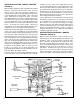
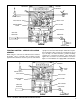
TYPICAL ANTILOCK - TRACTION SYSTEM
(PARTIAL)
Reservoir air pressure is constantly present at the traction
solenoid. When the electronic controller detects wheel spin
it energizes the solenoid and in response the solenoid opens
momentarily. While the solenoid is open, air is delivered
through internal passages to the double check valve. The
check valve diaphragm flexes in response and seals the
passage to the open exhaust of the brake valve. Once past
the double check valve, air from the solenoid flows through
the rest of the valve in the same manner as a normal service
brake application and air is delivered out the delivery ports
of the ATR-2
™
valve.
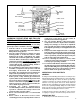
When the electronic controller de-energizes the solenoid,
air between the solenoid and the double check valve returns
to the solenoid and is exhausted. Air between the relay
piston and double check valve is exhausted at the brake
valve while delivery pressure is exhausted at the main
ATR-2
™
valve’s exhaust port.
PREVENTIVE MAINTENANCE
GENERAL
Perform the tests and inspections presented at the
prescribed intervals. If the ATR-2
™
valve fails to function as
described, or leakage is excessive, it should be repaired or
replaced with a new or genuine Bendix remanufactured unit,
available at any authorized parts outlet.
EVERY 3 MONTHS, 25,000 MILES OR 900
OPERATING HOURS
1. Remove any accumulated contaminates and visually
inspect the exterior for excessive corrosion and physical
damage.
2. Inspect all air lines connected to the ATR-2
™
valve for
signs of wear or physical damage. Replace as
necessary.
3. Test air line fittings for excessive leakage and tighten or
replace as necessary.
4. Perform the Leakage Test described in this manual.
EVERY YEAR, 100,000 MILES, OR 3,600
OPERATING HOURS
1. Perform the Operation and Leakage Tests described in
this manual.
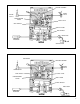
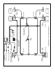
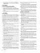
FIGURE 10 - BOBTAIL TRAILER SERVICE BRAKES RELEASING
CONTROLLER
BRAKE
VALVE
CHECK VALVE
RELAY PISTON
INLET EXHAUST
REAR AXLE
RESERVOIR
TRAILER SUPPLY
PROPORTIONING
PISTON
TRACTION
SOLENOID
INLET EXHAUST
SERVICE BRAKE
MODULATOR
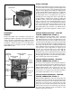
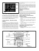
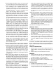
FIGURE 9 - ATR-2
™
VALVE PRESSURE DELIVERY CURVE
Tractor
Trailer
Combination
Service Brake Chamber Pressure
0 psi
0 psi
Service Port Pressure
Bobtail
Tractor
EXHAUST