Bendix™ BlindSpotter® Side Object Detection System Installation Guide Bendix™ BlindSpotter® Side Object Detection System BW2798 (Formerly VOIG0032) April 2013
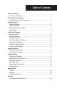
General Table ofInformation Contents General Information Warnings and Cautions........................................................................................2 FCC Compliance Statement Federal Communications Commission .................................................................4 System Overview Product Description .............................................................................................5 System Operation ......................................................................
General Information Warnings and Cautions ! WARNING ▲ Improper use of this system could lead to a serious accident. Read this entire Installation Guide before operating the Bendix™ BlindSpotter® system. Pay particular attention to the safety messages below. This guide should be used in conjunction with proper training. Limitations of Collision Warning Systems The Bendix™ BlindSpotter® rear collision warning system is intended solely as an aid for an alert and conscientious professional driver.
General Information ! WARNING ▲ People’s lives depend on the proper installation of this product in conformance with these instructions. It is necessary to read, understand, and follow all instructions shipped with the product. Failure to follow all safety precautions and instructions may result in property damage, serious injury, or death. The Bendix™ BlindSpotter® system is intended for commercial use.
FCC Compliance Statement Federal Communications Commission This device complies with Part 15 of the FCC (Federal Communications Commission) rules. Operation is subject to the following two conditions: (1) This device may not cause harmful interference and (2) this device must be able to accept any interference received, including interference that may cause undesired operation.
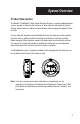
System Overview Product Description The Bendix™ BlindSpotter® Side Object Detection System is a pulse-modulated radar system capable of detecting the presence of other vehicles along side of the host vehicle, aiding the driver's ability to avoid collisions while merging into adjacent lanes of traffic. A visual indicator, placed on the windshield pillar near the side view mirror provides the driver with an additional tool for checking lane clearance next to the vehicle before merging.
System Operation System Operation The Bendix™ BlindSpotter® Side Object Detection System is powered by the vehicle's ignition switch, and consists of a pulse-modulated radar sensor mounted to the side of the vehicle coupled to a cab mounted display unit, that constantly monitors the area within the radar's view for any objects present that may pose a collision hazard during a lane change.
System Operation Side Object Detection Display The display unit has two bright LED indicators used to display the system status. A yellow LED indicates when the system is active, and a red LED indicates an object is detected. An ambient light sensor automatically controls the intensity of the two status LEDs, dimming them in low light conditions. The display unit's built-in speaker provides an audible alert if an object is detected when the vehicle's turn signal is activated.
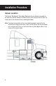
Installation Procedure Sensor Location The Bendix™ BlindSpotter® Side Object Detection Sensor should be mounted on the side of the vehicle, between 22 and 36 inches from the ground and at least 18 inches rear of the side view mirror (see diagram below).
Installation Procedure Sensor Orientation The Bendix™ BlindSpotter® Side Object Detection Sensor should be orientated so the embossed logo is parallel to the ground (see diagrams below). Orientation is crucial for proper operation due to the radar's polarized beam profile.
Installation Procedure Mounting the Sensor The sensor should be mounted to the vehicle using 10-24 (6 mm) stainless steel hardware. Bolts should be installed from the sensor side, with flat washers and nylock nuts on the backside. Torque hardware to a maximum of 22 lbs. in. Do not over torque.
Installation Procedure Side Object Display Mounting The Bendix™ BlindSpotter® Side Object Detection Display Unit should be mounted on the inside of the cab to the windshield pillar. The display unit should be positioned in line with the side view mirror on the same side of the vehicle as the sensor without obstructing the driver's view. ! WARNING ▲ The Side Object Display Unit is not weather proof and must be mounted on the inside of the cab.
Installation Procedure Component Connectors OPERATOR DISPLAY UNIT 4 1 ODU P1 3 2 CONNECTOR REAR SIDE OBJECT DETECTION SENSOR 6 1 5 2 4 3 CONNECTOR REAR 12
Installation Procedure Harness Connector Pin-Out J1 - Deutsch Part Number DT04-4P Pin 1 J2 - Pin 4 Pin 2 J2 - Pin 5 Pin 3 J2 - Pin 3 Pin 4 Turn Signal Input J2 - Deutsch Part Number DT04-6P Pin 1 Ignition Power Pin 2 Chassis Ground Pin 3 J1 - Pin 3 Pin 4 J1 - Pin 1 Pin 5 J1 - Pin 2 Pin 6 Not Used 13
Installation Procedure Harness Layout Diagram 14
Operation Testing Testing System Operation 1. Before testing the system, move the vehicle to an area where there are no objects within a minimum of a 15-foot radius of the sensor. 2. Turn the vehicle's ignition to the on position (do not start vehicle). ! WARNING ▲ Observe proper safety procedures by making sure the vehicle's parking brakes are set and the engine is off before performing any tests. 3.
Operation Testing Testing Sensor Detection To test the sensor's maximum effective detection capabilities, use a flat metallic object with a minimum surface area of one (1) square foot, and hold it facing the sensor at the following positions using the diagram below as a reference. 1. Six (6) feet out from center. 2. Six (6) feet out, six feet left from center. 3. Six (6) feet out, six feet right from center. 4. Ten (10) feet from center (maximum effective distance).
Troubleshooting System Fault Indication If both the red and yellow LEDs remain illuminated continuously after five seconds of initial power-up, or anytime during normal operation, this is an indication that the system has detected a failure with the radar sensor or a loss of communications between the sensor and the side sensor display. 1. Disconnect the sensor and the side object display from the harness and check the connectors for corrosion, or damage to the harness. 2.
Troubleshooting Red Detection LED Remains On If after the initial five second system power-up test, the red detect indicator remains illuminated constantly, even when no objects are present in the radar sensors detection zone, either the radar sensor is improperly mounted or has malfunctioned. 1. Review the sensor installation section in this manual to verify proper sensor positioning, orientation, and mounting. 2.
Troubleshooting No Objects Detected If after the initial system power-up the sensor does not appear to detect any objects, the radar sensor may have malfunctioned. Refer to the Testing System Operation section in this manual. 1. Hold and aim a test object six (6) feet out from center, directly at the sensor, and verify if the side object display indicates the object has been detected. 2.
General Information Troubleshooting No Audible Tone When an object is detected while the vehicle's turn signal is active, but the side object display does not emit an audible tone, either the system is improperly wired or the side object display has malfunctioned. 1. With the vehicle's ignition switch in the off position, disconnect the display connector (J1) and use an ohm meter to test the continuity between pin 1 and the turn signal source point. J1 Display 2.
Troubleshooting System Does Not Power-Up When the vehicle's ignition switch is turned to the on position and the side object display fails to power-up, either the system's fuse has blown, the harness is wired improperly or damaged, or the system has malfunctioned. 1. Check the system's inline one amp fuse. 2. With the vehicle's ignition switch in the off position, disconnect the sensor connector (J2). Use a voltmeter to test for ignition voltage between pins 1 and 2.
SIDE OBJECT DETECTION SENSOR 22 INTERCONNECT HARNESS J1 ODU GROUND IGNITION TURN SGNL ODU PWR ODU GND ODU COMM TURN SIGNAL CONNECTOR REAR 3 2 4 1 J1 Display ODU PWR ODU GND COMM PWR GND CONNECTOR REAR 4 3 5 2 6 1 J2 Sensor J2 SOD ODU P1 OPERATOR DISPLAY UNIT Troubleshooting Wiring Diagrams
1 2 3 SIDE SENSOR SENSOR CONNECTOR FRONT 6 5 4 J2 3 4 5 GND COMM ODU PWR ODU GND 6 1 2 PWR BROWN DK GREEN WIRING DIAGRAM RED BLACK WHITE RED BLACK TURN SIGNAL J2 SOD GROUND IGNITION ORANGE WHITE BROWN DK GREEN 1 2 4 3 TURN SIG ODU COMM ODU GND ODU PWR OPERATOR DISPLAY UNIT 240 INCHES TURN SGNL 72 INCHES J1 ODU IGNITION GROUND 1 2 DISPLAY CONNECTOR FRONT 4 3 J1 Troubleshooting 23
Specifications Typical: Electronics Solid state Sealing Encapsulated to protect from dust, moisture, and vibration. Operating Temperature -40°F to +185°F (-40°C to +85°C) Sensor Pulsed RF transmitter at 5.8 GHz Material Weight Dimensions Mounting Polycarbonate radome with aluminum back plate 1.25 lbs. (0.57 kg) 5.25" (13.3 cm) diameter x 1.375" (3.5 cm) deep 3 - 0.188 (4.8 mm) diameter mounting holes Operator Display Unit (ODU) Material Weight Dimensions Mounting Polycarbonate / ABS alloy .25 lbs.
Specifications Regulatory Compliance: Compliant with FCC Part 15.
Warranty Manufacturer Limited Warranty The Bendix standard warranty specific to retrofit systems is 12 months/100,000 miles when the product is installed on its intended application. The limited warranty does not cover defects or damage caused by abuse, misuse, road debris, accidents or improper installation, maintenance or service. Note: Some exclusions do apply. Refer to the Bendix Limited Warranty VORAD® Collision Warning System (BW2759) for complete warranty information visit www.bendix.
27
Bendix Commercial Vehicle Systems LLC 901 Cleveland Street Elyria, Ohio 44035 1-800-247-2725 BW2798 ©2013 Bendix Commercial Vehicle Systems LLC, a member of the Knorr-Bremse Group All Rights Reserved • 04/13