SD-61-4960 Bendix® Wingman® Advanced™ (FLR20™ Sensor) DESCRIPTION WARNING Improper use of the Bendix® Wingman® Advanced™ system can result in a collision causing property damage, serious injuries, or death. The driver is always responsible for the control and safe operation of the vehicle at all times. The Bendix Wingman Advanced system does not replace the need for a skilled, alert professional driver, reacting appropriately and in a timely manner, and using safe driving practices.
If the vehicle in front of you slows down below the cruise control’s set speed, the Bendix® Wingman® Advanced™ system will intervene and, as necessary, in this order: (a) reduce the engine throttle; then (b) apply the engine retarder; then (c) apply the foundation brakes, in an attempt to maintain the set following distance behind the vehicle ahead. NOTE: If during the intervention, it is necessary to apply the foundation brakes, the vehicle will not automatically resume the cruise control set speed.
KEY CONTENTS (See the full index on pages 60-59) Operation . . . . . . . . . . . . . . . . . . . . . . . . . . . . . . . . . . . 3-10 What to Expect When Using the Bendix Wingman Advanced System. . . . . . . . . . . . . . . . . . . . . . 5-6 1.5 How the Driver Interacts with Bendix Wingman Advanced. . . . . . . . . . . . . . . . . . . . . 7 1.8 Alerts and Warnings. . . . . . . . . . . . . . . . . . . . . . . . . . . 8-10 2.0 Maintenance. . . . . . . . . . . . . . . . . . . . . . . . . . . . . . . .
AUTOMATIC FOUNDATION BRAKE APPLICATIONS Also see the Alerts and Warnings section of this manual for more detailed information about the alerts. The vehicle automatically manages foundation brake priorities among the various vehicle systems that use the foundation brakes, such as Bendix® Wingman® Advanced™ system, Bendix ® ESP ® Electronic Stability Program, Bendix® ATC (Automatic Traction Control) and Bendix® ABS (Antilock Braking System).
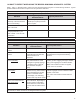
1.4 WHAT TO EXPECT WHEN USING THE BENDIX® WINGMAN® ADVANCED™ SYSTEM Table 1, parts 1-3, illustrate what to expect from the Wingman Advanced system in various driving situations. Typical system indications and actions to expect from the system are illustrated. What to Expect (1.4) Part One: All driving scenarios (Cruise is either “on” or “off”) Typical System Indication/Alerts Situation A broken-down vehicle is stationary in the lane in which the truck is traveling.
What to Expect (1.4) Part Two: Cruise control “on” and speed “set” Typical System Indication/Alerts Situation Going down a grade with a detected forward vehicle. DO NOT USE cruise control on downhill grades. Typical System Actions DO NOT USE cruise control on downhill grades. Cruise control should NOT be used on downhill grades - see page 3. (See the CDL manual instructions on proper gear usage for downhill grades.
1.5 HOW A DRIVER INTERACTS WITH THE BENDIX® WINGMAN® ADVANCED™ SYSTEM Table 2 illustrates how the Wingman® Advanced™ system will respond to various actions a driver may take when using Wingman Advanced system on the road. The driver is always responsible for the control and safe operation of the vehicle at all times. The Bendix® Wingman® Advanced™ system does not replace the need for a skilled, alert professional driver, reacting appropriately and in a timely manner, and using safe driving practices.
THE FORWARD VEHICLE DETECTED ICON When cruise control is switched on and set and a vehicle ahead of you is detected by the radar, the detected forward vehicle icon — or similar — will illuminate on the vehicle dashboard. This is an indication to the driver that the Bendix® Wingman® Advanced™ system is actively managing the distance between your vehicle and the vehicle ahead, and may intervene automatically, if needed. See Figure 6 for examples. 1.
IMPACT ALERT (IA) FOLLOWING DISTANCE ALERT (FDA) The Impact Alert is the most severe warning issued by the Bendix® Wingman® Advanced™ system. This alert indicates that a collision with the detected forward vehicle is likely and the driver must immediately act to potentially avoid, or lessen the severity of, a collision. The Following Distance Alert (FDA) provides both audible and visual alerts whenever the time between your vehicle and the detected forward vehicle ahead is less than one and a half (1.
The driver should be especially careful when approaching certain types of vehicles or objects. The Wingman Advanced radar may not be able to detect vehicles and objects with limited metal surfaces (such as recreational vehicles, horse-drawn buggies, motorcycles, logging trailers, etc.). NOTE: Entering a curve may reduce the alert time to less than three (3) seconds. Advanced system foundation brake applications for at least 20 minutes.
2.0 MAINTENANCE SECTION Section Index 2.1 General Safety Guidelines . . . . . . . . . . . 11 2.2 Equipment Maintenance: Brake System and ABS Functionality . . . . . . . . . . . . . 12 2.3 2.4 System Preventive Maintenance . . . . . . . 12 Additional Support at www.bendix.com . . . . 12 2.
2.2 EQUIPMENT MAINTENANCE: BRAKE SYSTEM AND ABS FUNCTIONALITY Importance of Antilock Braking System (ABS) Maintenance – Optimal Bendix® Wingman® Advanced™ system braking requires a properly maintained ABS system, without any active ABS Diagnostic Trouble Codes (DTCs). Have active DTCs repaired by a qualified technician. Any ABS DTCs will cause Wingman Advanced to deactivate.
3.0 INTRODUCTION TO TROUBLESHOOTING SECTION This section introduces three initial steps to accurately troubleshoot the Bendix® Wingman® Advanced™ system. FOR FLR10 RADAR SENSORS, SEE SD-61-4962. Section Index 3.1 Troubleshooting Basics . . . . . . . . . . . . 13 3.2 Narrowing Down the Problem . . . . . . . 14-15 3.3 Overview of Possible Issues . . . . . . . . . 16 We recommend reading this introductory section, as well as the Troubleshooting/Diagnostics Section (4.
3.2 NARROWING DOWN THE PROBLEM Use the questions found in Table 3.2 below to help assess if the Bendix® Wingman® Advanced™ system is not performing correctly. Be sure to have a thorough understanding of the system’s normal behavior; this will reduce the troubleshooting time. The table provides a guide to basic troubleshooting questions and possible corrective actions. Items in Italics cross-reference to the service procedures in this manual to repair the condition described.
Narrowing Down the Problem (3.2) Questions Next Steps Did the radar sensor currently on the vehicle come from another vehicle? The radar sensor may be incompatible with the new vehicle. Follow Section 1.10: Radar Sensor Interchangeability procedure and check system trouble codes with Bendix® ACom® Diagnostics software. Read Section 4.3: Diagnostic Trouble Codes. With cruise control set, does the system consistently apply the foundation brakes when a forward vehicle slows? This is normal operation.
3.3 OVERVIEW OF POSSIBLE ISSUES Some customer issues are actually misunderstandings of how the Bendix® Wingman® Advanced™ system performs normally. Use Table 5 below to learn the causes of potential issues if Wingman Advanced is not performing correctly. Some issues can be investigated by a visual inspection. Others may cause a diagnostic trouble code (DTC) to be logged: See Section 4.3: Diagnostic Trouble Codes. Overview of Possible Issues (3.
4.0 TROUBLESHOOTING/ DIAGNOSTICS SECTION 4.1 BENDIX® ACOM® DIAGNOSTICS SOFTWARE FOR FLR10 RADAR SENSORS, SEE SD-61-4962. Bendix ® ACom® Diagnostics is a PC-based software program available as a free download from the Bendix web site (www.bendix.com) or on a CD from the online Bendix Literature Center (order BW2329). This software provides the technician with access to all the available ECU diagnostic information and configuration capability.
The Bendix® ACom® Diagnostics for ABS User Guide is available for download at www.bendix.com and should be used as a reference to all functions of the ACom service tool. In general, the protocol for Wingman Advanced is described as CAN or CAN 250. (See Figure 15 for an example of an adapter compatible with Wingman Advanced). The Bendix® EC-60™ controller protocol will be described as J1708, J1587, or Unified Diagnostic Services (UDS). 4.
4.3 TABLE OF BENDIX® WINGMAN® ADVANCED™ DIAGNOSTIC TROUBLE CODES (DTCs) NOTE: FLR10 RADAR SENSORS USE DIFFERENT DTCS — SEE SD-61-4962. Refer to column one for the DTC(s) found and determine the Service Action Code(s) to take.
Table of Diagnostic Trouble Codes (DTCs), Causes and Recommended Actions for FLR20 Radars Description Go to the Service Action Code List in Table 6B DTC SPN FMI 96 97 98 99 100 101 104 105 106 107 108 109 110 111 112 113 114 115 116 886 886 886 886 886 886 886 886 886 886 886 886 886 886 886 886 886 886 886 14 14 14 14 14 14 14 14 14 14 14 14 14 14 14 14 14 14 14 J1939 Signal Error: J1939 Signal Error: J1939 Signal Error: J1939 Signal Error: J1939 Signal Error: J1939 Signal Error: J1939 Signal Error
Table of Diagnostic Trouble Codes (DTCs), Causes and Recommended Actions for FLR20 Radars DTC SPN FMI 140 141 142 143 144 145 146 147 148 149 150 158 159 160 161 162 163 164 165 166 167 168 169 170 171 172 173 174 175 176 177 178 179 181 182 183 184 185 186 187 188 189 190-193 886 886 886 886 886 886 886 886 886 886 886 886 886 886 886 886 886 886 886 886 886 886 886 886 886 886 886 886 886 886 886 886 886 886 886 886 886 886 886 898 898 898 886 14 14 14 14 14 14 14 14 14 14 14 14 14 14 14 14 14 14 14
Table 6B: Action Code and the Recommended Service to Use Service Action Letter Recommended Service (FLR20 Radar Sensors Only) A Possible causes: • Some error conditions may occur at extreme high or low temperatures. These trouble codes must be diagnosed with the ambient temperature above 32°F (0°C) and below 100°F (38°C). Perform the following: • Clear the Wingman Advanced trouble codes using the procedure in Section 4.4: Clearing Diagnostic Trouble Codes (DTCs).
Table 6B: Action Code and the Recommended Service to Use Service Action Letter Recommended Service (FLR20 Radar Sensors Only) F This DTC is not an indicator of a malfunctioning sensor. Do not replace the sensor. Possible causes: • The system was used improperly, such as use of the system on downhill grades. Perform the following: • Check any engine, or engine retarder trouble codes. • Clear the Wingman Advanced trouble codes using the procedure in Section 4.4: Clearing Diagnostic Trouble Codes (DTCs).
Table 6B: Action Code and the Recommended Service to Use Service Action Letter Recommended Service (FLR20 Radar Sensors Only) L This DTC is not an indicator of a malfunctioning sensor. Do not replace the sensor. Possible causes: • Mounting offset incorrect. Perform the following: • Check the mounting offset of the radar sensor in ACom® Configuration screen. The offset value should not exceed 500 mm. • If the error returns, call Bendix for assistance at 1‑800‑AIR‑BRAKE (1‑800‑247-2725, option 2).
Table 6B: Action Code and the Recommended Service to Use Service Action Letter Recommended Service (FLR20 Radar Sensors Only) P This DTC is not an indicator of a malfunctioning sensor. Do not replace the sensor. Possible causes: • The Wingman system finds an expected J1939 source, but the signal’s value is out of the normal operating range. Review the following sections: • 1.10: Radar Sensor Interchangeability • 4.
4.4 CLEARING DIAGNOSTIC TROUBLE CODES (DTCs) Power Supply Pin Codes (4.5) This procedure must be used when troubleshooting the diagnostic trouble codes shown in Table 6. Clear the Wingman® Advanced™ system Diagnostic Trouble Codes (DTCs) using the Bendix® ACom® service tool. Click the “Clear” button located on the “Read /Clear Fault Codes” screen. Using ignition power only, power off the vehicle for at least 1 minute. Next, start the engine and run it at idle for at least 15 seconds.
4.7 ENGINE COMMUNICATIONS (J1939) TEST PROCEDURE The Bendix® Wingman® Advanced™ system requires several J1939 messages from the engine ECU to control the engine and retarder torque for distance control and braking. The Wingman Advanced system will set a diagnostic trouble code if one of these messages is not present.
5.0 OTHER SYSTEM FEATURES SECTION Section Index 5.1 Reading Bendix® Wingman® Advanced™ System Key Indicators . . . . . . . . . . . . 28 5.2 Diagnostic Trouble Code (DTC) Self-Clearing . . . . . . . . . . . . . . . . . 5.3 Following Distance Adjustment Switch (Optional) . . . . . . . . . . . . . . . . . . . 28 5.4 Configuring Wingman Advanced Following Distance Alerts . . . . . . . . . . . . . . . . 5.
5.4 CONFIGURING BENDIX® WINGMAN® ADVANCED™ FOLLOWING DISTANCE ALERTS Multiple alert and distance setting strategies, known as Following Distance Alert (FDA) configurations, can be chosen using the Bendix® ACom® Diagnostics tool. In current versions of ACom software, the service technician will find a selection box called “Configuration Number” which gives the service technician the choices shown in Figure 18 and in Table 8.
5.5.3 EXTRACTING DATA AND SAVING A REPORT The Bendix ACom Diagnostics tool and User Guide is available online at “ABS Software” link under “Services and Support” on the Bendix website (www.bendix.com). After a successful connection, the service technician will be presented with the window shown in Figure 20. Selec t “ St ar t AC B Dat a Lo g”. T he ser vic e technician will be asked to enter the vehicle ID and mileage. This data will be stored in the report. See Figure 20.
FIGURE 22 - TYPICAL WINGMAN ADVANCED VEHICLE REPORT
APPENDIX A - RADAR MOUNTING Appendix A Bendix FLR20™ Radar Mounting ® GENERAL WARNING: Improper use of the Bendix® Wingman® Advanced™ system can result in a collision causing property damage, serious injuries, or death. WARNING: Under no circumstances must the radar be removed or repositioned from the original production line installation. The assembly should always be mounted in the original OEM location.
Appendix A Bendix® FLR20™ Radar Mounting A3 BENDIX® FLR20™ RADAR SENSOR MOUNTING CLEARANCE • CAUTION: Vehicle equipment, including bumpers, deer guards, etc. must not infringe upon the zone used by the radar sensor to emit and receive radar waves. Failure to comply with this requirement will impair the function of the radar. Only vehicle OEM-approved covers and/or cover panels may be installed directly in front of the radar.
APPENDIX B - RADAR ALIGNMENT Appendix B Bendix FLR20™ Radar Alignment ® B1.0 RADAR ALIGNMENT ALIGNMENT FLOWCHART For Bendix® FLR10™ radar sensors, see SD-61-4962. Use this flowchart to find which section(s) of this Appendix to use.
Appendix B Bendix FLR20™ Radar Alignment ® B1.1 GENERAL INFORMATION ABOUT ADJUSTING THE ALIGNMENT Accurate vertical and lateral alignment of the radar sensor is critical for proper operation of Bendix® Wingman® Advanced™. If the alignment is outside a certain range it could cause false warnings, missed warnings and a diagnostic trouble code in the system.
Appendix B Bendix FLR20™ Radar Alignment ® B2 LATERAL ALIGNMENT USING THE LEARNED ALIGNMENT SCREEN This is the preferred and recommended method for lateral alignments This method is for vehicles with Bendix® DIU® displays that use software whose version is 12.220 and above. To verify the DIU’s software version go to the Volume screen, where it is displayed in the top right-hand corner.
Appendix B Bendix FLR20™ Radar Alignment ® B3 LATERAL ALIGNMENT USING BENDIX® ACOM® DIAGNOSTICS Use this method to align the Bendix FLR20 laterally when the vehicle does not have a DIU, or has a DIU (but its software version is prior to 12.220) B3.1 Tools needed: Bendix ACom Diagnostics, and a Torx T-20 Screwdriver B3.2 Connect the vehicle to a laptop computer with the current release of the Bendix ACom Diagnostics software. B3.3 See the “Alignment Value” shown on the Configuration screen.
Appendix B Bendix FLR20™ Radar Alignment ® B3 LATERAL ALIGNMENT USING BENDIX® ACOM® DIAGNOSTICS (CONTINUED) B3.4 See the image below to see the lateral alignment adjustment screw location. Use Table in B3.3 to find the number of full turns of the stand-off adjustment screw required to bring the radar sensor back into alignment. A Torx T-20 screwdriver with a mark or other indicator may help track the number of turns.
Appendix B Bendix FLR20™ Radar Alignment ® B4 VERTICAL ALIGNMENT USING AN INCLINOMETER B4.1 B4.2 B4.3 Tools Needed: A digital inclinometer, Torx T-20 screwdriver. (If a clip from the Bendix Alignment Tool kit is available, the clip may be placed over the front of the radar sensor during this process.) Park the vehicle on a level floor. Air suspensions must be charged and stable. Calibrate (or “zero”) the inclinometer on a horizontal section of the frame rail.
APPENDIX C - RADAR ALIGNMENT USING BENDIX® ALIGNMENT CLIP AND TOOL Appendix C Bendix FLR20™ Radar Alignment ® C1 LATERAL ALIGNMENT USING THE BENDIX® ALIGNMENT CLIP AND TOOL This is the method to use for lateral alignment when a radar and/or bracket is replaced. Tools needed: Bendix® alignment kit, steel clip, Torx T-20 screwdriver and a tape measure. • One of the Bendix® Alignment Tools part no: K065284 and K096579 — available from Bendix parts outlets — are used.
Appendix C Bendix FLR20™ Radar Alignment ® LATERAL ALIGNMENT USING THE BENDIX® ALIGNMENT CLIP AND TOOL (CONTINUED) C1.4 Locate symmetrical points on the front of the vehicle that are at least 12 inches from the vehicle’s center line (such as the tow hooks). Using a ruler or tape measure, record the distance from each side to the laser light line.
Appendix C Bendix FLR20™ Radar Alignment ® C LATERAL ALIGNMENT USING THE BENDIX® ALIGNMENT CLIP AND TOOL (CONTINUED) NOTE: Complete these steps only if a lateral adjustment is necessary. C1.7 With the Bendix alignment tool still in place, use the Torx T-20 screwdriver to turn by hand the driver‑side stand-off adjustment screw until the desired alignment is reached IMPORTANT: Do not adjust this stand-off!! Use a Torx T-20 screwdriver here to adjust for the lateral alignment C1.
Appendix D Bendix FLR20 Radar Dynamic Alignment Method This procedure may be used in rare cases where the stored alignment value is not available. The vehicle must have a DIU with a software version 12.220 or above. LATERAL ALIGNMENT USING THE DYNAMIC ALIGNMENT METHOD Use the flowchart B1 to be sure you are using the correct alignment procedure. This procedure is used in the rare cases where a learned alignment value is not available.
APPENDIX E - TROUBLESHOOTING CHECKLIST Appendix E Troubleshooting Checklist Detailed Scenarios and Tests Record Driver’s Answers for Follow-up with Bendix Does the vehicle maintain its set speed when cruise control is switched on and set? Yes No _____________ Is the cruise control “set” icon displayed? Yes No _____________ Yes No _____________ While following a forward vehicle within radar range and the cruise control switched on and set, observe the following: Is the forward vehicle detected i
Appendix E Troubleshooting Checklist Detailed Scenarios and Tests Record Driver’s Answers for Follow-up with Bendix With cruise engaged, and a faster vehicle passes your vehicle on the left or right on a straight or slightly curvy road: Does your vehicle throttle up and try to keep pace with the faster moving vehicle? Yes No _____________ Does it give a following distance alert? Yes No _____________ Yes No _____________ Yes No _____________ Yes No _____________ Yes No _____________ Yes
APPENDIX F - DRIVER INTERFACE UNIT (DIU): DISPLAYS AND ALERTS Appendix F Bendix® Driver Interface Unit (DIU): Displays & Alerts F1 Operator Interface The Bendix® Wingman® Advanced™ system is either integrated into the vehicle's dash or console, or uses the Bendix® Driver Interface Unit (DIU) to communicate with the driver. (For integrated systems, see the vehicle operator’s manual for more information.) This Section describes the functions of the DIU.
Appendix F Bendix® Driver Interface Unit (DIU): Displays & Alerts When the initialization sequence is complete, the following screen is displayed for approximately 3 seconds to indicate the features available to the driver. (No LEDs Illuminated) Bendix Wingman ACB Wingman Adv. Next, the DIU will enter normal operation. Under normal operation, the screen is: (No LEDs Illuminated) If the Bendix® Wingman® Advanced™ goes into self-test mode, the DIU may briefly display the “Bendix SelfTest” screen.
Appendix F Bendix® Driver Interface Unit (DIU): Displays & Alerts F1.3 Volume Selecting “Volume” from the main menu displays the following screen: (No LEDs Illuminated) The driver uses the up ( this menu item. )/down ( Volume ) arrow buttons to change the volume. Pressing the “OK” button exits The modified volume setting will be retained through ignition cycles unless configured not to do so. If not configured, the volume setting will default to 100% on each new ignition cycle.
Appendix F Bendix® Driver Interface Unit (DIU): Displays & Alerts F1.6 US/Metric From this menu item, the user may select whether English or Metric units are displayed. For instance, in “metric” mode, the following distance is shown in meters. In “US” mode, the following distance is shown in feet. F1.
Appendix F Bendix® Driver Interface Unit (DIU): Displays & Alerts F2.0 Driver Demonstration Mode Selecting Demo from the main menu starts a demonstration mode that shows the various lights, display screens, and sounds produced by the DIU – along with a brief explanation of their meaning – for the configured features. Pressing the down ( ) arrow button advances through the screens. The up ( ) arrow button has no functionality in this mode. The mode may be exited at any time by pressing the OK button.
Appendix F Bendix® Driver Interface Unit (DIU): Displays & Alerts F3.1 Object Detected When there is no valid object detected and no other high priority alert is displayed, the DIU will stand by with the following screen: (No LEDs Illuminated) When a valid object is detected, and is outside the range of the first level of alert, and no other higher priority alert is displayed, the DIU will display the following and no audio tones will be issued.
Appendix F Bendix® Driver Interface Unit (DIU): Displays & Alerts F3.4 Following Distance Alert (FDA) Level 3 (Fast audible two-tone alert/three yellow LEDs illuminated) The DIU provides the driver with audio and visual alerts for as long as the vehicle ahead is in this zone and traveling at the same speed or slower. This is the closest and most urgent Following Distance Alert. The DIU will not display following distance while in an FDA Level.
Appendix F Bendix® Driver Interface Unit (DIU): Displays & Alerts F4.0 Impact Alert (IA) The “Impact Alert”, uses a combination of distance to the vehicle ahead, plus high relative velocity, to decide when to issue a loud solid tone, as well as a visual indicator to the driver.
Appendix F Bendix® Driver Interface Unit (DIU): Displays & Alerts F6.0 ACB Icon The ACB icon appears in the upper left-hand corner of the DIU’s screen to indicate to the driver that the adaptive cruise control with braking feature of the Bendix® Wingman® Advanced™ system is ready and able to intervene. Once the driver sets cruise, the DIU will display the set speed and the ACB icon as shown below.
Appendix F Bendix® Driver Interface Unit (DIU): Displays & Alerts F7.0 Brake Overuse Alert Using cruise control on downhill runs is the primary cause for this alert to be activated. Cruise control should NOT be used on downhill grades. Approach grades as you would normally, with the appropriate gear selected and at a safe speed.
APPENDIX G - HOW TO GENERATE, READ AND RESET THE BENDIX® WINGMAN® SYSTEM DIAGNOSTIC TROUBLE CODES USING BENDIX® ACOM® DIAGNOSTICS SOFTWARE Appendix G G1: How to Generate Wingman Diagnostic Trouble Code Report with ACom® Diagnostics ® 1. Select the Bendix® ACom® desktop icon 2. Select “Wingman” from the starter screen. Select “start with ECU” 3. Select “DTC”. 4. To generate the ACom report, select “Report”. For reference 5.
Appendix G G2: How to Read Wingman Diagnostic Trouble Code Reports with Bendix® ACom® Diagnostics ® 1. Select the Bendix® ACom® desktop icon 2. Select “Wingman” from the starter screen. Click “start with ECU” 3. Select “DTC”. 4. Select "Read". Active DTCs (diagnostic trouble codes) are shown along with descriptions of the codes and tests that can be run to troubleshoot the code. You can select “stored DTCs” also, to show inactive DTCs.
Appendix G G3: How to Clear Wingman Diagnostic Trouble Codes with Bendix® ACom® Diagnostics ® 1. Select the Bendix® ACom® Diagnostics desktop icon 2. Select “Wingman” from the starter screen. Select “start with ECU” 3. Select “DTC”. 4. C lick "Read". Active DTCs (diagnostic trouble codes) are shown along with descriptions of the codes and tests that can be run to troubleshoot the code. You can select “stored DTCs” also, to show inactive DTCs. For reference 5. Select “clear” to clear all active DTCs.
Appendix H How to Read Key System Indicators and Reset Alignment Values Read System Key Indicators (Configuration) 1. Start Bendix® ACom® Diagnostics and connect to vehicle. 2. Select “Advanced” and Click “Start with ECU” to display the “Advanced Status” window. 3.
Full Contents List 1.0 Operation Section 1.1 Important Safety Information . . . . . . . . . . . . . . . . . . . . 3 1.2 System Components . . . . . . . . . . . . . . . . . . . . . . . . 4 1.3 Activating the Bendix® Wingman® Advanced™ System . . . . . . .4 1.4 What to Expect When Using Bendix Wingman Advanced . . . . .5-6 1.5 How a Driver Interacts with Bendix Wingman Advanced . . . . . .7 1.6 Following Distance . . . . . . . . .
NOTES 5.0 Other System Features Section 5.1 Reading Bendix® Wingman® Advanced™ System Key Indicators . 28 5.2 Bendix Wingman Advanced Diagnostic Trouble Code (DTC) Self Clearing . . . . . . . . . . . . . . . . . . . . . . . . . . . . 28 5.3 Following Distance Adjustment Switch (Optional) . . . . . . . . . 28 5.4 Configuring Bendix Wingman Advanced Following Distance Alerts . . . . . . . . . . . . . . . . . . . . . . . . . . . . . . .
NOTES 62
NOTES 63
Log-on and Learn from the Best On-line training that's available when you are Visit www.brake-school.com. 24/7/365. Trademark acknowledgements: The ACOM, AD-IS, BENDIX, EC-60, ESP, and WINGMAN trademarks are licensed to or owned by Bendix Commercial Vehicle Systems LLC. Any references in this manual to MICROSOFT and any other company or trademark are solely for identification and cross reference purposes.