
User's Manual

37
Appendix B
Appendix B
Bendix
®
FLR20
™
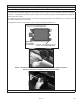
Radar Alignment
B3 LATERAL ALIGNMENT USING BENDIX
®
ACOM
®
DIAGNOSTICS
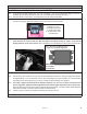
Use this method to align the Bendix FLR20 laterally when the vehicle
does not have a DIU, or has a DIU (but its software version is prior to 12.220)
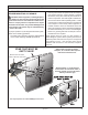
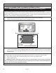
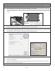
B3.1 Tools needed: Bendix ACom Diagnostics, and a Torx T-20 Screwdriver
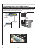
B3.2 Connect the vehicle to a laptop computer with the current release of the Bendix ACom Diagnostics software.
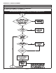
B3.3 See the “Alignment Value” shown on the Conguration screen.
If the alignment value shown by ACom Diagnostics is between -1.1° and 1.1 °, this is acceptable and the system
should operate normally. A value outside that range means the radar sensor should be adjusted.
BENDIX
®
ACOM
®
DIAGNOSTICS SCREEN SHOWING ALIGNMENT VALUE
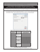
Alignment
Value Range
(Degrees)
Service Action
Number of Full Turns of
the Lateral Alignment
Adjustment Screw
-2.0 to -1.8
Adjustment
Required
6 clockwise
-1.7 to -1.6 5 clockwise
-1.5 to -1.2 4 clockwise
-1.1 to -0.8
No Adjustment
Needed
3 clockwise (optional)
-0.7 to -0.5 2 clockwise (optional)
-0.4 to -0.3 1 clockwise (optional)
-0.2 to 0.2
0.3 to 0.4 1 counterclockwise (optional)
-0.5 to 0.7 2 counterclockwise (optional)
0.8 to 1.1 3 counterclockwise (optional)
1.2 to 1.5
Adjustment
Required
4 counterclockwise
1.6 to 1.7 5 counterclockwise
1.8 to 2.0 6 counterclockwise
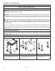
ADJUSTMENT SCREW ROTATION REQUIRED
Note: The maximum Alignment Value shown by ACom Diagnostics is two degrees (plus or minus).