
Service manual


46
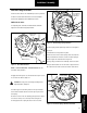
Figure 60. Upper and Lower Shoe Positioning
With Retainer Springs
Installed, Position
Upper and Lower Shoes
Around Anchor Pin
Shoe And Lining Installation
!
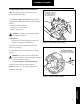
Figure 61. Shoe Return Spring Installation
Stretch Spring Using
Suitable Tool As Shown
!
!
Installation / Assembly
NOTE: The following procedures are divided into sections, identified
by brake model numbers.
ES-150-8D, F&6D
1. See Inspection & Repair / Replacement to verify that spider
camshaft, bracket, and brake adjuster are serviceable and properly
installed.
2. During shoe installation, lubricate:
• Shoe roller recess - one-piece roller.
CAUTION: Use only grease conforming to NLGI grade #1,
high-temperature, waterproof.
• Cam head surface. For efficient operation, this surface must
remain free of oil, grease or other contaminants.
3. Position upper shoe on anchor pin and cam.
4. Install retaining springs by butting bottom shoe against anchor pin
and top shoe. Install spring hooks in holes on webs. (Be sure hooks
are fully engaged before rotating lower shoe around anchor pin.)
5. Position upper and lower shoes around anchor pin. Refer to
Figure 60.
CAUTION: When the retaining spring passes the anchor pin,
the shoes may close very rapidly.
WARNING: The long term effects of non-asbestos fibers, have
not been determined. Therefore, precautions should be used
when handling these materials.
See General Information / Lining Material Warning
6. The shoes may close rapidly when the return spring hook passes
the center of the anchor pin (watch fingers.) Install a new shoe return
spring. On ES-150-6D steer brake install new return springs between
spring post and shoe with spring hooks towards the cam. Refer to
Figure 61.
NOTE: A lever or spring tool may be required to assist in hooking
shoe return spring.
Do Not Lubricate: