
User Guide


6
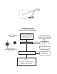
EC-13
™
Controller
M-12R
™
Modulator
(Remote
Mount)
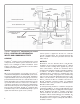
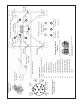
FIGURE 6 - EC-13
™
CONTROLLER AND M-12R
™
MODULATOR ASSEMBLY
3. Road test the trailer by making an antilock stop from a
vehicle speed of 20 miles per hour. When an antilock
stop is made, the modulator solenoids pulsate and an
audible burst of air can be heard. The wheels should
not enter a prolonged “lock” condition.
WARNING! PLEASE READ AND FOLLOW
THESE INSTRUCTIONS TO AVOID PERSONAL
INJURY OR DEATH:
When working on or around a vehicle, the following
general precautions should be observed at all times.
1. Park the vehicle on a level surface, apply the
parking brakes, and always block the wheels.
Always wear safety glasses.
2. Stop the engine and remove ignition key when
working under or around the vehicle. When
working in the engine compartment, the engine
should be shut off and the ignition key should be
removed. Where circumstances require that the
engine be in operation, EXTREME CAUTION should
be used to prevent personal injury resulting from
contact with moving, rotating, leaking, heated or
electrically charged components.
3. Do not attempt to install, remove, disassemble
or assemble a component until you have read
and thoroughly understand the recommended
procedures. Use only the proper tools and observe
all precautions pertaining to use of those tools.
4. If the work is being performed on the vehicle’s
air brake system, or any auxiliary pressurized air
systems, make certain to drain the air pressure
from all reservoirs before beginning ANY work
on the vehicle. If the vehicle is equipped with an
AD-IS
®
air dryer system or a dryer reservoir module,
be sure to drain the purge reservoir.
5. Following the vehicle manufacturer’s recommended
procedures, deactivate the electrical system in a
manner that safely removes all electrical power
from the vehicle.
6. Never exceed manufacturer’s recommended
pressures.
7. Never connect or disconnect a hose or line
containing pressure; it may whip. Never remove
a component or plug unless you are certain all
system pressure has been depleted.
8. Use only genuine Bendix
®
replacement parts,
components and kits. Replacement hardware,
tubing, hose, fi ttings, etc. must be of equivalent
size, type and strength as original equipment and
be designed specifi cally for such applications and
systems.
9. Components with stripped threads or damaged
parts should be replaced rather than repaired. Do
not attempt repairs requiring machining or welding
unless specifi cally stated and approved by the
vehicle and component manufacturer.
10. Prior to returning the vehicle to service, make
certain all components and systems are restored
to their proper operating condition.
11. For vehicles with Antilock Traction Control (ATC),
the ATC function must be disabled (ATC indicator
lamp should be ON) prior to performing any vehicle
maintenance where one or more wheels on a drive
axle are lifted off the ground and moving.
REMOVING EC-13
™
CONTROLLER ASSY
Locate the EC-13
™
controller on the trailer and determine
if it is mounted on a modulator (e.g. M-12
™
modulator) or is
remote mounted to a trailer frame member using a bracket.
Use the appropriate removal procedure below.
Removing the EC-13
™
Controller and M-12
™
Modulator:
1. Identify and remove all air lines connected to the
M-12
™
modulator.
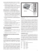
2. Disconnect the electrical connector (on the vehicle
wiring harness) from the EC-13
™
controller.
3. Note and mark the mounting position of the MC-13
™
modulator - controller assembly on the trailer. Loosen,
remove and save the nuts on the mounting hardware
that attaches the MC-13
™
modulator controller bracket
to the trailer. Remove the MC-13
™
modulator - controller
assembly from the trailer.
4. Remove as much contamination as possible from
the exterior of the assembly making sure to keep the
contamination away from the open ports.
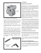
5. Note and mark the position of the EC-13
™
controller
relative to the M-12
™
modulator. Remove and retain the
four hex cap screws that secure the EC-13
™
controller
to the M-12
™
modulator. Carefully separate the EC-13
™
controller from the M-12
™
modulator enough to expose
the wire harness that connects both units electrically.
Disconnect the wire harness by separating the four pin
connector at the EC-13
™
controller. Peel the gasket from
the EC-13
™
controller or M-12
™
modulator and retain
for reuse. Note: Use a new gasket if damaged during
removal or if a new gasket is immediately available.