Service Manual Trucks Group 59 Anti-Lock Brake System (ABS) Bendix VNL, VNM PV776-TSP29984/1
Foreword The descriptions and service procedures contained in this manual are based on designs and methods studies carried out up to April 98. The products are under continuous development. Vehicles and components produced after the above date may therefore have different specifications and repair methods. When this is believed to have a significant bearing on this manual, supplementary service bulletins will be issued to cover the changes. The new edition of this manual will update the changes.
Contents General .................................................................................................... 3 Anti-Lock Brake System .......................................................................... 3 General Safety Information .................................................................... 3 Specifications ......................................................................................... Electronic Control Unit .................................................................
ABS Sensor Adjustment ...................................................................... Front Axle Sensor Replacement ......................................................... Removal ............................................................................................. Installation ......................................................................................... Rear Axle Sensor Replacement .......................................................... Removal ..............................
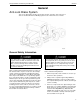
Group 59 Anti-Lock Brake System (Bendix) General General Anti-Lock Brake System This service information describes the design, function, operation, and service procedures for the Bendix Anti-Lock Braking System used on Volvo VN series vehicles. W5000526 General Safety Information Some brake linings contain non-asbestos fibers, the long term effects of which are unknown. Some older original equipment brake linings contain asbestos fibers, a cancer and lung disease hazard.
Group 59 Anti-Lock Brake System (Bendix) 4 Clean brake parts and assemblies in the open air. During disassembly, carefully place all parts on the floor to avoid getting dust into the air. Use an industrial vacuum cleaner with a HEPA filter system to clean dust from the brake drums, torque plate (spider), and other brake parts. After using the vacuum, remove any remaining dust with a rag soaked in water and wrung until nearly dry. 5 DO NOT grind or machine the brake linings.
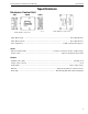
Group 59 Anti-Lock Brake System (Bendix) Specifications Specifications Electronic Control Unit W5000952 W5000537 Bendix ABS ECU, current model Bendix ABS ECU, early model Make, Model (early) ...................................................................................................................... EC-16 (Bendix AL-6) Make, Model (current) ...................................................................................................................
Group 59 Anti-Lock Brake System (Bendix) Specifications Modulator Valve W5000518 Make, model ............................................................................................................................................... Bendix, M-22 Relay Valve W5000371 Make, Model (for tractors without traction control) ................................................................................... Bendix, BP-R1 Make, Model (for tractors with traction control) ...................................
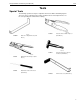
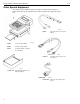
Group 59 Anti-Lock Brake System (Bendix) Tools Tools Special Tools The following special tools may be required for work on the Anti-Lock Braking System. The tools can be ordered from the vendor specified in the tool description. Please use the corresponding tool number when ordering.
Group 59 Anti-Lock Brake System (Bendix) Tools Other Special Equipment The following special equipment may be required for troubleshooting the Anti-Lock Brake System and can be ordered from the vendor specified in the equipment description.
Group 59 Anti-Lock Brake System (Bendix) Tools W5000945 W0001488 J-42883 Sensor pin-out cable (Kent-Moore) Fluke 87 Digital Multimeter (John Fluke Mfg. Corp.
10
Group 59 Anti-Lock Brake System (Bendix) Design and Function Design and Function System Description The Bendix Anti-Lock Braking System (ABS) is an electronically controlled system that continually monitors wheel speed and controls wheel braking during extreme braking situations, such as during hard braking or slippery road conditions. The ABS is an important component of the foundation brake system and works in conjunction with the standard vehicle braking system.
Group 59 Anti-Lock Brake System (Bendix) When the ECU senses that a wheel or set of wheels is about to lock during braking, a signal is sent to the appropriate solenoid modulator valve to intermittently open and close it. This opening and closing occurs rapidly (as many as 15 times per second) to reduce brake pressure and ensure that the wheel returns to rotating while still maintaining most of the brake capacity.
Group 59 Anti-Lock Brake System (Bendix) Design and Function Tooth Wheel The tooth wheel is an alloy ring that resembles a gear. It normally has 100 teeth cut into its surface. The purpose of the teeth are to cause a pulsating current flow in the sensor circuit. As each tooth passes near the sensor, it causes a small current to flow in the sensor. When the gap between two teeth is in front of the sensor, the current flow stops.
Group 59 Anti-Lock Brake System (Bendix) Design and Function Sensor The sensor is a magnetic inductor that allows current to flow through it from the ECU when one of the wheel teeth is in front of it. It continuously provides wheel speed information to the ECU whenever the ignition is ON, regardless of whether or not the vehicle is in motion. The sensors are installed in brackets that are bolted to the brake spider. Each sensor is held in the bracket by a spring clip.
Group 59 Anti-Lock Brake System (Bendix) Design and Function Modulator Valve The Bendix M-22 modulator valve is a high capacity air solenoid valve. It has two solenoid coils. One of the coils is energized to isolate the brake chamber from the brake system air supply and vent the brake pressure from the brake chamber. The other coil is energized to isolate the brake chamber from the brake system supply and hold the pressure that is in the brake chamber.
Group 59 Anti-Lock Brake System (Bendix) Design and Function ABS Electronic Control Unit (ECU) The ECU is the brain of the ABS system. It receives wheel speed information from the sensors and sends signals to the ABS modulator valves. The ECU is powered through a 30–amp fuse on the ignition circuit. The ECU receives power only when the ignition is ON. The ECU compares the wheel speed of each wheel to the speed of the other wheels to determine if any one wheel is locked up (i.e.
Group 59 Anti-Lock Brake System (Bendix) The ECU houses a magnetic switch that is used to erase faults from memory once they have been repaired. A fault is erased from memory (ECU reset) by holding a magnet next to the ECU where it is labeled RESET (just below the VLT LED). The magnet must be capable of lifting a 3 oz. weight in order to perform the reset function. While the magnet is held against the ECU all LEDs will illuminate.
Group 59 Anti-Lock Brake System (Bendix) Design and Function Electrical Fuses The ABS circuit is fused through a 30–amp fuse on the main fuse panel which is located behind the fuse panel cover. The power to operate the ABS comes from the ignition. The ABS Warning Lamp Relay (R3) is also powered through this same 30–amp fuse. (For connection details, refer to “ABS System Diagram, VOLVO Engine” page 75 or “ABS System Diagram, Vendor Engine” page 76.
Group 59 Anti-Lock Brake System (Bendix) Design and Function Connectors The ABS ECU connectors include one 18–pin and one 30–pin Metri-pack 150 Series connector. The modulator valve connectors are 3 pin Packard 280 Series. The pinout designations for each of the ECU connectors are located in “ABS System Diagram, Vendor Engine” page 76.
Group 59 Anti-Lock Brake System (Bendix) Design and Function Instrumentation ABS Warning Light An amber ABS warning light is provided in the instrument cluster (center section). Its function is to notify the operator that the ABS system has detected an unusual condition or fault in the system. The lamp will illuminate under the following conditions. • The ignition switch is turned to ON (The lamp will go off when the vehicle speed reaches approximately 11 km/h (7 mph).
Group 59 Anti-Lock Brake System (Bendix) Design and Function Wheel Spin Indicating Light A yellow TCS warning light is provided on the instrument cluster (right section). This light is associated with both TCS and ABS. The light has several functions. If the TCS switch is in the OFF (up) position, the TCS light will come on to remind the driver that the TCS is selected to OFF. If TCS is not installed, the light will blink once per second anytime drive wheel spin is detected.
Group 59 Anti-Lock Brake System (Bendix) Design and Function Traction Control System (TCS) The ABS on a vehicle may also be configured for traction control. The Traction Control System (TCS) uses the same wheel sensors as the ABS to determine if one set of drive wheels is spinning much more rapidly than those on the other side.
Group 59 Anti-Lock Brake System (Bendix) Design and Function ABS Fault Detection During operation, the ABS continuously monitors the system for faulty conditions. The system components are checked to ensure they are in working order. If the ABS detects that a fault has occurred, as determined by the absence of correct signals from one of the ABS components, the system illuminates the ABS warning lamp.
24
Group 59 Anti-Lock Brake System (Bendix) Troubleshooting Troubleshooting General Troubleshooting There are three methods for performing troubleshooting of the ABS: 1 Use the diagnostic display on the Data Link instrument cluster. This is also the simplest method. (See “Data Link Instrument Cluster — Diagnostic Display” page 26.) 2 Use the MPSI Pro-Link 9000. (See “MPSI Pro-Link 9000” page 29.) 3 Use the ECU LEDs. (See “ECU LEDs” page 44.
Group 59 Anti-Lock Brake System (Bendix) Troubleshooting Data Link Instrument Cluster — Diagnostic Display The integrated multi-function display of the Dixson Data link instrument cluster can be used to display diagnostic messages from the ABS. The system uses the SAE J1708/1587 data link and is installed in most vehicles with electronically controlled engines. D I A G N Diagnostic Menu The Data Link diagnostic LCD display receives information from the ABS ECU.
Group 59 Anti-Lock Brake System (Bendix) Troubleshooting Diagnosing Faults Using the Data Link Diagnostics The following is a list of the possible faulty component messages for the Instrument Cluster Data Link diagnostic display (Line 2): Message Component Location ABS ABS ABS ABS ABS ABS ABS ABS ABS ABS ABS ABS ABS ABS ABS Steering axle, left side Steering axle, right side Forward drive axle, left side Forward drive axle, right side Rear drive axle, left side Rear drive axle, right side Steering axle,
Group 59 Anti-Lock Brake System (Bendix) To view diagnostic messages for the ABS, perform the following: 1 Stop the engine. 2 Turn the ignition key to ON. 3 Press the MODE button on the vehicle dash until the message “Diagnostics Menu” is displayed. D I A G N 4 Diagnostic Menu Press the SET button to have the datalink retrieve data. D I A G N Retrieving data Please Wait... 5 Press the down arrow, then wait until a new message is displayed. 6 Repeat Step 5 until the ’Brakes’ display appears.
Group 59 Anti-Lock Brake System (Bendix) Troubleshooting MPSI Pro-Link 9000 PERSONAL INJURY HAZARD! Before working on a vehicle, set the parking brakes, place the transmission in neutral, and block the wheels. Failure to do so can result in unexpected vehicle movement and can cause serious personal injury or death. Exhaust gases contain deadly poison. When testing a vehicle with the engine running, conduct the test outdoors or use a properly vented exhaust hose.
Group 59 Anti-Lock Brake System (Bendix) Troubleshooting EC-16 (AL-6) The MPSI Pro-Link 9000 is available from Kent-Moore. The Bendix ABS cartridge is required to use the ProLink 9000 on the Bendix ABS model EC-16 (AL-6). Refer to the Tools section for part numbers for the MPSI Pro-Link 9000 and the Bendix ABS cartridge. W5000943 1 2 MPSI Pro-Link 9000 Bendix ABS cartridge 1 2 3 MPSI Pro-Link 9000 MPC Data Cartridge Application Card EC-17 (AL-7) The Pro-Link 9000/MPC tool is available from MPSI.
Group 59 Anti-Lock Brake System (Bendix) Troubleshooting Readout Window The Pro-Link 9000 uses a liquid crystal display (LCD). The readout contains 4 display lines with 20 characters each and can include letters, numbers, and special symbols. The display includes a built-in backlight so that the display can be read in any light. When the readout window shows a menu, the first three display lines shows the menu title and other helpful information. The last display line shows the first menu choice.
Group 59 Anti-Lock Brake System (Bendix) Troubleshooting Installing and Removing the MPC Cartridge With the MPC cartridge installed in the Pro-Link tool, you can use the Bendix ABS application card. To Install the MPC Cartridge: 1 Disconnect the vehicle adapter (containing the 12– volt power feed) from the vehicle. 2 Seat the cartridge on the back of the Pro-Link tool. Do not hold the cartridge at an angle. It must sit flat. It will go only one way.
Group 59 Anti-Lock Brake System (Bendix) Troubleshooting Power/Data Cable The data and power cable must be connected to the vehicle or an external 12–volt power source before the Pro-Link/MPC tool can function. Connecting the Power/Data Cable Earlier cables consisted of a single assembly; both the data cable and power cable are attached by a single molded connector. Later versions have two separate cables. In both cases, the power cable includes a cigarette lighter adapter.
Group 59 Anti-Lock Brake System (Bendix) Troubleshooting Application Cards Application cards are specific to the vehicle’s computer system. Before beginning work on the vehicle, check the identification label on the application card to make sure you are using the correct vehicle application. Installing the Application Card: Slide the application card into the PCMCIA card slot on the MPC cartridge. The card will seat into the MPC cartridge only one way. Do not force the card into place.
Group 59 Anti-Lock Brake System (Bendix) Troubleshooting Diagnosing Faults Using the Pro-Link 9000 PERSONAL INJURY HAZARD! Before working on a vehicle, set the parking brakes, place the transmission in neutral, and block the wheels. Failure to do so can result in unexpected vehicle movement and can cause serious personal injury or death. Exhaust gases contain deadly poison. When testing a vehicle with the engine running, conduct the test outdoors or use a properly vented exhaust hose.
Group 59 Anti-Lock Brake System (Bendix) Troubleshooting Using the Bendix ABS Application Card and MPC Cartridge (with EC-17/AL7 ECU) Perform the following steps to determine faults using the Pro-Link 9000. 1 Insert the MPC cartridge into the Pro-Link 9000 (see “Installing and Removing the MPC Cartridge” page 32). 2 Plug the male end of the data cable into the Pro-Link 9000. Tighten the thumbscrews to secure the cable.
Group 59 Anti-Lock Brake System (Bendix) 8 The Diagnostic Codes menu lets you choose from the following diagnostic functions: • • • • Troubleshooting 12 Using the up or down arrow keys, scroll to the “Test System” option. Active Faults Fault History Clear Fault History Clear Active Faults BENDIX ABS/ATC VERSION 1.
Group 59 Anti-Lock Brake System (Bendix) 14 Using the up or down arrow keys, scroll to the “ECU Information” option. BENDIX ABS/ATC VERSION 1.00 " - - - - Selections - - - - # ECU INFORMATION To select the “Reset ECU” option, press ENTER. This function displays information about the ECU being tested. Press FUNCTION to exit back to the main option menu. 38 Troubleshooting 15 Press the FUNCTION key when finished to end the session.
Group 59 Anti-Lock Brake System (Bendix) Troubleshooting MPC Application Menu Structure The application menu structure will assist you in locating specific functions of the Bendix ABS/ATC application card.
Group 59 Anti-Lock Brake System (Bendix) Troubleshooting Using the Bendix ABS Cartridge (with EC-16/AL-6 ECU) Perform the following steps to determine faults using the Pro-Link 9000. 1 Insert the Bendix ABS cartridge into the Pro-Link 9000/MPC tool. 2 Plug the male end of the data cable into the Pro-Link 9000. Tighten the thumbscrews to secure the cable. 3 Remove the dust cap from the vehicle diagnostics connector and connect the data cable to the diagnostics connector (1) on the vehicle.
Group 59 Anti-Lock Brake System (Bendix) 12 If there are any faults of the type selected, the ProLink 9000 will display them one at a time, such as in the example below. Troubleshooting CLR ACTIVE FAULTS ARE YOU SURE ? LEFT FRONT SENSOR ! [NO] YES SENSOR OPEN " A1 DEV: 11 FLT: 01 # The last line of the display provides information regarding the fault. In the example, “A1” refers to the number of the Active fault assigned by the ECU. “H1” would refer to the first fault stored in the fault History.
Group 59 Anti-Lock Brake System (Bendix) Troubleshooting System Testing Using the Pro-Link 9000 (EC-16/AL-6) There are several tests that can be run on the Bendix system using the MPSI Pro-Link 9000.
Group 59 Anti-Lock Brake System (Bendix) 11 When the ABS selections menu appears, use the down arrow key to scroll to TEST SYSTEM. Then press ENTER. ABS MENU - - - - - SELECTIONS - - - - " TEST SYSTEM # 12 Use the up and down arrow keys to scroll to the test of your choice, then press ENTER to run the test. 13 When system testing is complete, press FUNC to return to the selections menu. Use the up or down arrow keys to scroll to DATA LIST, then press ENTER.
Group 59 Anti-Lock Brake System (Bendix) Troubleshooting ECU LEDs The condition of specific ABS/TCS components is provided by a series of LED’s on the side of the ECU housing. If an error condition is detected within the system by the ECU, one or more of the LEDs will light to show the location and component associated with the fault. There are ten LEDs plus a magnetically activated reset switch in the ECU diagnostics.
Group 59 Anti-Lock Brake System (Bendix) Troubleshooting W5000553 45
Group 59 Anti-Lock Brake System (Bendix) Troubleshooting W5000967 46
Group 59 Anti-Lock Brake System (Bendix) Troubleshooting W5000940 47
Group 59 Anti-Lock Brake System (Bendix) Troubleshooting W5000959 Note: For more detailed information, refer to Electrical Wiring and Circuit Diagrams 48
Group 59 Anti-Lock Brake System (Bendix) Troubleshooting W5000620 Note: For more detailed information, refer to Electrical Wiring and Circuit Diagrams 49
Group 59 Anti-Lock Brake System (Bendix) Troubleshooting W5000621 Note: For more detailed information, refer to Electrical Wiring and Circuit Diagrams 50
Group 59 Anti-Lock Brake System (Bendix) Troubleshooting W5000622 Note: For more detailed information, refer to Electrical Wiring and Circuit Diagrams 51
Group 59 Anti-Lock Brake System (Bendix) Troubleshooting W5000960 Note: For more detailed information, refer to Electrical Wiring and Circuit Diagrams 52
Group 59 Anti-Lock Brake System (Bendix) Troubleshooting W5000961 Note: For more detailed information, refer to Electrical Wiring and Circuit Diagrams 53
Group 59 Anti-Lock Brake System (Bendix) Troubleshooting W5000625 Note: For more detailed information, refer to Electrical Wiring and Circuit Diagrams 54
Group 59 Anti-Lock Brake System (Bendix) Troubleshooting W5000626 Note: For more detailed information, refer to Electrical Wiring and Circuit Diagrams 55
Group 59 Anti-Lock Brake System (Bendix) Troubleshooting W5000968 Note: For more detailed information, refer to Electrical Wiring and Circuit Diagrams 56
Group 59 Anti-Lock Brake System (Bendix) Troubleshooting W5000963 Note: For more detailed information, refer to Electrical Wiring and Circuit Diagrams 57
Group 59 Anti-Lock Brake System (Bendix) Troubleshooting W5000629 58
Group 59 Anti-Lock Brake System (Bendix) Troubleshooting W5000964 Note: For more detailed information, refer to Electrical Wiring and Circuit Diagrams 59
Group 59 Anti-Lock Brake System (Bendix) Troubleshooting W5000965 Note: For more detailed information, refer to Electrical Wiring and Circuit Diagrams 60
Group 59 Anti-Lock Brake System (Bendix) Troubleshooting W5000966 Note: For more detailed information, refer to Electrical Wiring and Circuit Diagrams 61
62
Group 59 Anti-Lock Brake System (Bendix) Service Procedures Service Procedures ABS Sensor Adjustment 2 Special tools: J-42942 CAUTION 1 Potential sensor damage. DO NOT use a hammer to drive the sensor into position. Hammering the sensor could cause the sensor to be inoperative. Press the sensor toward the wheel hub until the sensor contacts the tooth wheel. 3 Remove the sensor adjustment tool.
Group 59 Anti-Lock Brake System (Bendix) Front Axle Sensor Replacement Service Procedures 5 Remove the brake drum. Removal 6 PERSONAL INJURY HAZARD! Before working on a vehicle, set the parking brakes, place the transmission in neutral, and block the wheels. Failure to do so can result in unexpected vehicle movement and can cause serious personal injury or death. CAUTION Possible sensor damage. DO NOT pull on the sensor cable in order to remove it. This may damage the sensor.
Group 59 Anti-Lock Brake System (Bendix) 9 Disconnect the sensor from the vehicle wiring at the connector closest to the sensor. 10 Pull the sensor cable through the hole in the frame rail. Service Procedures 3 CAUTION Potential sensor damage. DO NOT us a screwdriver or sharp instrument to insert sensor. Use of a sharp instrument could cause sensor damage. Using the sensor tool press the sensor into the spring clip and mounting block.
Group 59 Anti-Lock Brake System (Bendix) Rear Axle Sensor Replacement Removal PERSONAL INJURY HAZARD! Before working on a vehicle, set the parking brakes, place the transmission in neutral, and block the wheels. Failure to do so can result in unexpected vehicle movement and can cause serious personal injury or death. 1 Park the vehicle on a level surface, apply the parking brake, and block the front wheels. Ensure the vehicle ignition is OFF and transmission is in neutral.
Group 59 Anti-Lock Brake System (Bendix) 3 CAUTION Service Procedures Front Modulator Valve Replacement Potential sensor damage. DO NOT us a screwdriver or sharp instrument to insert sensor. Use of a sharp instrument could cause sensor damage. Using the ABS sensor tool (see “ABS Sensor Adjustment” page 63), press the sensor into the spring clip and mounting block. Press the sensor toward the hub until it contacts the tooth wheel. 4 Connect the sensor cable to the chassis harness.
Group 59 Anti-Lock Brake System (Bendix) Service Procedures 5 Remove the valve mounting screws and nuts. 5 Build up air pressure in the vehicle’s air system. 6 Remove the valve. 6 Release the parking brakes. 7 Note the orientation of the fittings in the valve, then remove the fittings. 7 Apply normal brake pressure and verify that the air passes freely through the ABS modulator valve and that there are no air leaks. Installation 1 Install the proper fittings on the valve in the original orientation.
Group 59 Anti-Lock Brake System (Bendix) Service Procedures Rear Modulator Valve Replacement 5 Removal PERSONAL INJURY HAZARD! Before working on a vehicle, set the parking brakes, place the transmission in neutral, and block the wheels. Failure to do so can result in unexpected vehicle movement and can cause serious personal injury or death. 1 Park the vehicle on a level surface, apply the parking brake, and block the wheels. Ensure vehicle ignition is OFF and transmission is in neutral.
Group 59 Anti-Lock Brake System (Bendix) Service Procedures ATR Valve Replacement 5 PERSONAL INJURY HAZARD! Before working on a vehicle, set the parking brakes, place the transmission in neutral, and block the wheels. Failure to do so can result in unexpected vehicle movement and can cause serious personal injury or death. Removal W5000534 Connect the supply line from the relay valve to port 1 of the modulator valve. 6 Connect the valve electrical connector.
Group 59 Anti-Lock Brake System (Bendix) Installation ABS Electronic Control Unit Replacement 1 Install the proper fittings on the valve in the original orientation. Use tape or paste type thread sealant on fittings to reduce the probability of leakage. 2 Mount the valve on the vehicle using two cap screws and nuts. Torque the nuts to 24 Nm (18 ft-lb). Service Procedures Removal 1 Ensure the vehicle ignition is OFF. 24 Nm (18 ft-lb) 2 Disconnect all connectors from the ECU.
Group 59 Anti-Lock Brake System (Bendix) 7 Configure the ECU by holding a magnet over the point labeled RESET on the LED side of the ECU for at least 20 seconds. Note: The LEDs will flash while selfconfiguration is taking place. Power should not be removed from the ECU during self-configuration. 8 Verify that the LEDs flash to indicate self-configuration is occurring. 9 When self-configuration is complete, verify the ECU carries out its normal power on sequence as listed below. a. All LEDs ON b.
Group 59 Anti-Lock Brake System (Bendix) System Check System Check Function Checks Note: Unless otherwise stated, there must be air pressure in the brake system to perform the valve tests described below. Note: If any of the desired results for the tests below are not met the valve should be repaired or replaced. Traction Control Valve Function Check PERSONAL INJURY HAZARD! Before working on a vehicle, set the parking brakes, place the transmission in neutral, and block the wheels.
Group 59 Anti-Lock Brake System (Bendix) System Check Traction Control Valve Differential Pressure Check 1 Apply 10 psi pressure to the traction control valve service port. Note the pressure at the delivery port. 4 Deplete the air from the system and remove the test gauges. 2 Subtract the delivery port value from 10 psi. This is the differential pressure. 5 Restore the system to normal. 3 Verify the differential pressure is correct for the valve part number.
Group 59 Anti-Lock Brake System (Bendix) System Check System Diagrams ABS System Diagram, VOLVO Engine W5001000 75
Group 59 Anti-Lock Brake System (Bendix) System Check ABS System Diagram, Vendor Engine W5000999 76
Group 59 Anti-Lock Brake System (Bendix) System Check Chassis and ECU Connectors CHASSIS PASS THRU 30–PIN CONNECTOR CAVITY D1 D3 D5 D7 E1 K2 K4 K6 K8 FUNCTION TRACTION CONTROL ENABLE SIGNAL RETARDER RELAY SIGNAL TCS LAMP SIGNAL ABS LAMP RELAY SIGNAL 12 VOLT SUPPLY SAE J1587/1708 DATA LINK (+) SAE J1587/1708 DATA LINK (-) TRACTION CONTROL SAE J1922 (=) TRACTION CONTROL SAE J1922 (-) Note: Connector is shown from insertion-side.
Group 59 Anti-Lock Brake System (Bendix) System Check Vendor engine ECU connectors VOLVO ENGINE ECU (78–PIN CHASSIS PASS THRU) CONNECTOR CAVITY M5 M6 H4 H6 H8 FUNCTION J1922 J1922 J1939 (HIGH) J1939 (Shielded) J1939 (LOW) CIRCUIT 406 408 407 CATERPILLAR ENGINE ECU CONNECTOR CAVITY 3 9 FUNCTION J1922 J1922 CUMMINS ENGINE ECU CONNECTOR CAVITY N P FUNCTION J1922 J1922 DDEC ENGINE ECU CONNECTOR CAVITY A B 78 FUNCTION J1922 J1922
Feedback One of our objectives is that workshop personnel should have access to correct and appropriate service manuals where it concerns fault tracing, repairs and maintenance of Volvo trucks. In order to maintain the high standards of our literature, your opinions and experience when using this manual would be greatly appreciated.
Volvo Trucks North America, Inc. P.O. Box 26115, Greensboro, NC 27402-6115 Volvo Trucks Canada, Ltd. 6490 Vipond Drive, Mississauga, Ontario L5T 1W8 http://www.volvotrucks.volvo.com PV776-TSP29984/1 (1500) 4.98 © Volvo Trucks North America, Inc.