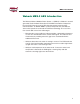
MBS-2 Installation Guide AUGUST 2002 Heavy Duty Trailer ABS by Wabash National ®
Notes, Cautions, and Warnings This manual contains Notes, Cautions, and Warnings in addition to the assembly instructions. Notes: Provide additional comments to help with installation and set up. Cautions: Provide notification of situations that can cause damage to machinery and tools. Warnings: Provide alerts to situations that can cause personal injury or death. Please take the time to read and understand this manual before beginning assembly.
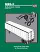
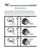
MBS-2 Installation ® MBS Identification Before service or diagnostics is performed on a Wabash MBS unit, the system design must be verified. Do not rely on labels or verbal descriptions to identify the MBS system. Refer to the illustration below and compare the marking in the lower right-hand corner of the ECM with the location(s) of the wheel speed sensor wire or cable on the trailer’s axle(s). Make sure to properly identify the Wabash MBS; flash codes and system components are different for each system.
MBS-2 Installation ® Contents Wabash MBS-2 ABS Introduction . . . . . . . . . . . . . . . . . . . . . . . . . . . . . . . . 1 MBS-2 System Components . . . . . . . . . . . . . . . . . . . . . . . . . . . . . . . . . . . . 2 General Air Brake Requirements . . . . . . . . . . . . . . . . . . . . . . . . . . . . . . . . . 5 ABS . . . . . . . . . . . . . . . . . . . . . . . . . . . . . . . . . . . . . . . . . . . . . . . . . . . . . . . . . 6 Key Dates . . . . . . . . . . . . . . . . . . . . . . . . . . . . .
MBS-2 Installation ® Wabash MBS-2 ABS Introduction The Wabash National Modular Brake System –2 (MBS-2) is Wabash’s second generation Trailer Antilock Brake System. All MBS-2 controllers incorporate the new PLC (power line carrier) data link that permits tractor to trailer communications. In addition MBS-2 systems incorporate the new Wabash active wheel speed sensor based on Hall Effect technology.
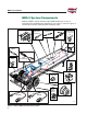
MBS-2 Installation ® MBS-2 System Components Wabash’s MBS-2 system includes unique ABS components as well as interfacing with standard trailer components (see Figure 1). Refer to Figures 2 and 3 for part number and description of Wabash parts.
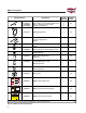
MBS-2 Installation ® Component Item Description Quantity Required Supplied in Kit 1 yes 1 no 10800316 10800317 2S-1M w/168" Power Cable 2S-1M w/30" Power Cable 10800318 10800319 2S-2M w/168" Power Cable 2S-2M w/30" Power Cable 10800320 10800321 4S-1M w/168" Power Cable 4S-1M w/30" Power Cable 10800315 10800324 4S-2M Side-by-Side w/168" Power Cable 4S-2M Side-by-Side w/30" Power Cable 10800322 10800323 4S-2M Axle-by-Axle w/168" Power Cable 4S-2M Axle-by-Axle w/30" Power Cable 14401905 MBS
MBS-2 Installation ® Component Item Bolt 1/4-20 x 3-1/2" Grade 8 (1M System) Bolt 1/4-20 x 5-1/2" Grade 8 (2M System) Nut 1/4-20 Nylon Insert Locknut Washer 1/4" SAE Flat 2 2 2 2 yes yes 14401359 ABS Wiring Harness 1 yes 14401744 ABS Malfunction Lamp Harness w/Diagnostic Switch 1 yes 14200428 Yellow ABS Malfunction Lamp Green TL-30 Series Trailer Warning Lamp Red TL-30 Series Trailer Warning Lamp 1 yes 1 no TO READ STORED FAULT PRESS THREE TIMES (HOLD 3RD PRESS FOR THREE SECONDS) X4 TO
MBS-2 Installation ® General Air Brake Requirements FMVSS-121 identifies minimum requirements for air brake systems on commercial vehicles built in the U.S. (Requirements in Canada are covered under CMVSS-121 and are virtually identical.) These regulations cover requirements for new construction.
MBS-2 Installation ® ABS Key Dates March 1, 1997 Tractors must be equipped to provide full time power to trailers. March 1, 1998 Newly manufactured trailers must be equipped with ABS. Some special use cases are exempt. (Refer to FMVSS-121 for specific details.) April 1, 2000 ABS required on newly manufactured Canadian Vehicles March 1, 2001 Trailer malfunction lamp is required in the tractor cab. March 1, 2008 Trailer mounted malfunction lamp no longer required.
MBS-2 Installation ® Power Requirements for ABS For trailers built after March 1 of 1998, the trailer wiring system must provide two sources of power for the antilock system. 1. Full-time power (when ignition is on) must be provided by the tractor. This full-time power source may be shared with other trailer circuits. The SAE J560 Blue (AUX) circuit is commonly used as the full-time power source. In other cases, a separate ISO 3731 connector is provided. 2. Brake light power.
MBS-2 Installation ® Color and Labeling The malfunction indicator lamp must be yellow in color and identified with the letters “ABS” to distinguish the lamp from other yellow side markers. The letters may be on the lens, on the lens housing, or on the trailer itself, near the lamp. Intensity and Photometric Requirements The external ABS malfunction indicator lamp must conform to SAE-J592 JUN92. Trailers shall use a combination clearance/side marker lamp marked with a “PC” or “P2”.
MBS-2 Installation ® Applications The performance of the Wabash MBS-2 ABS depends upon proper installation of all components. Trailer suspension, axle configuration, and other brake components will affect the level of ABS performance. The “Sensed” and the “Controlled” axles must be considered prior to installation of the MBS-2. Wabash recommends the following guideline for typical MBS-2 installations. When locating the sensors on the tandem, choose the axle that locks up first during hard braking.
MBS-2 Installation ® SPRING SUSPENSION SENSED AXLE SENSED AXLE MBS-2 #10800316 CONTROLLED AXLE SENSED AXLE AIR SUSPENSION 2S-1M MBS-2 #10800316 CONTROLLED AXLE SENSED AXLE MBS-2 #10800316 MBS-2 #10800316 CONTROLLED AXLES CONTROLLED AXLES SENSED AXLE SENSED AXLE MBS-2 #10800317 Air Suspended Dollies Not Commonly Available CONTROLLED AXLE CONTROLLED AXLE SENSED AXLE MBS-2 #10800317 SENSED AXLE MBS-2 #10800317 MBS-2 #10800317 Air Suspended Dollies Not Commonly Available CONTROLLED AXLE
MBS-2 Installation ® SPRING SUSPENSION SENSED AXLES AIR SUSPENSION 4S-1M SENSED AXLES MBS-2 #10800320 MBS-2 #10800320 CONTROLLED AXLES CONTROLLED AXLES SENSED AXLES SENSED AXLES MBS-2 #10800320 CONTROLLED AXLES SPRING SUSPENSION SENSED AXLES CONTROLLED AXLES 4S-2M Side Control MBS-2 #10800315 CONTROLLED AXLES One valve each side AIR SUSPENSION One valve each side CONTROLLED AXLES SENSED AXLES MBS-2 #10800315 CONTROLLED AXLES SENSED AXLES Air Suspended Dollies Not Commonly Available
MBS-2 Installation ® Electrical System The Antilock Control Module (ACM) consists of an Electronic Control Module (ECM) and a Pneumatic Control Module (PCM) combined as one unit. However, they are individually field replaceable. The wheel sensor, malfunction lamp, and power harness circuits are connected to the ECM.
MBS-2 Installation ® Pneumatic System The PCM contains the pneumatic solenoids that physically control pressure in the service line to the relay valve. The 3/8" service line enters and exits the PCM through integrated quick connect fittings. The PCM also incorporates a quick exhaust valve that minimizes delays during brake release and helps purge contaminants that may enter the service control line.
MBS-2 Installation ® Installation of Electrical System Power and Sensor Cables One power cable, one or two sensor cables, and one accessory cable are integrated into the MBS-2. The power cable runs to the Weather Pack 5-way connector on the trailer. The sensor cables terminate in three-pin connectors that mate with the 3-pin active speed Sensor Cable. The accessory cable terminates in a Deutsch 4-pin DTM series connector.
MBS-2 Installation ® ECM PCM Wheel Sensor Accessory Power 281UX025 Figure 9, MBS-2 Components and Connectors 15
MBS-2 Installation ® Front R R MBS-2 2S-1M In-Axle Sensor Cable Routing S S 10800283 Roadside Left MBS-2 Roadside In-Axle Sensor Grey Connector Plugs Into the ABS Power Cable Accessory Cable Roadside Sensor Cable Curbside Sensor Cable Grommet Grommet Curbside In-Axle Sensor Axle Plug Wave Washer Black Connector Bolt Sensor Cable C Route Sensor Cable As Shown S C S Front 10800282 Curbside Right 281UX011 Figure 10, MBS-2 In-Axle Sensor Cable Routing for 2S-1M Systems 16
MBS-2 Installation ® Front R R MBS-2 2S-2M In-Axle Sensor Cable Routing S S 10800283 Roadside Left MBS-2 Roadside In-Axle Sensor Grey Connector ABS Cable Plugs Into the ABS Power Cable Accessory Cable Roadside Sensor Cable Curbside Sensor Cable Grommet Grommet Curbside In-Axle Sensor Axle Plug Wave Washer Black Connector Bolt Sensor Cable C Route Sensor Cable As Shown S C S Front 10800282 Curbside Right 281UX033 Figure 11, MBS-2 In-Axle Sensor Cable Routing for 2S-2M Systems 17
MBS-2 Installation ® Front R R MBS-2 4S-1M In-Axle Sensor Cable Routing S S 10800283 Roadside Left MBS-2 Roadside In-Axle Sensor Grey Connector Roadside Sensor Cable Grey Connector ABS Cable Plugs Into the ABS Power Cable Curbside Sensor Cable Accessory Cable Grommet Curbside In-Axle Sensor Wave Washer Axle Plug Bolt Grommet Black Connector Front C S C S 10800282 Curbside Right Sensor Cable Route Sensor Cable As Shown 281UX010 Figure 12, MBS-2 In-Axle Sensor Cable Routing for 4S-1M 1
MBS-2 Installation ® Front R R MBS-2 4S-2M In-Axle Sensor Cable Routing S S 10800283 Roadside Left MBS-2 Roadside In-Axle Sensor Grey Connector Roadside Sensor Cable ABS Cable Plugs Into the ABS Power Cable Accessory Cable Grommet Grey Connector Curbside Sensor Cable Curbside In-Axle Sensor Wave Washer Axle Plug Bolt Grommet Black Connector Front C S C S 10800282 Curbside Right Sensor Cable Route Sensor Cable As Shown 281UX005 Figure 13, MBS-2 In-Axle Sensor Cable Routing for 4S-2M 1
MBS-2 Installation ® Circuit Requirements The solenoid valves used in the Wabash MBS products allow higher airflow and require less voltage and current than most trailer ABS systems. For a nominal 12-volt supply, current consumption is about 1.25 amperes maximum during ABS activity. Satisfactory operation is available down to 7 volts. The MBS-2 minimizes trailer issues caused by inadequate voltage (typically found in 3-trailer units).
MBS-2 Installation ® Pneumatic System MBS-2 Location and Mounting The MBS-2 can be located some distance from the relay valve. The air line connecting the PCM to the relay valve should be 3 to 5 feet in length. This allows some mounting flexibility, provides good ABS performance, and complies with brake application and release timing requirements. Mount the MBS-2 using two grade 8 bolts WNC part number BLT00650 (1/4-20 x 3-1/2") for 1M systems, BLT00732 (1/4-20 x 5-1/2") for 2M systems.
MBS-2 Installation ® Plumbing Instructions Install the MBS-2 as follows: 1. Select a suitable mounting location near the front of the bogie. 2. Install the MBS-2 in the blue service line (see Figure 16). 3. Connect the port marked “SUP” to the glad-hand side. 4. Connect the port marked “DEL” to the relay valve side. NOTE: Because of volume considerations discussed later, the spring brake valve may be supplied from either the “upstream” (glad-hand side) or the “downstream” (relay side) of the MBS-2.
MBS-2 Installation ® Preferred Plumbing 2M Side Control Spring Suspension w/Slider TEV Supply Service MBS-2 Relay Valves Bulkhead Feedthru Spring Brake Gladhand Service Brake Note: Actual Component Locations May Vary Preferred Plumbing 2M Axle Control Spring Suspension w/Slider 281UX014 TEV Supply Service MBS-2 Relay Valves Bulkhead Feedthru Gladhand Spring Brake Service Brake Note: Actual Component Locations May Vary 281UX016 Figure 16, MBS-2 “Downstream” Air Supply Configurations (Preferr
MBS-2 Installation ® NOTE: If the plumbing cannot be accomplished within the five foot maximum length, the relay valve can be fed directly with a 3/8" tube from the “DEL” port of the MBS-2. The feed for the trailer spring brake valve can be taken from a tee connection upstream of the MBS-2. Use a 3/8" line to the Trailer Emergency Valve (TEV). For this configuration, the volume of the line to the spring brake valve is not included in the calculation.
MBS-2 Installation ® Alternate Plumbing 2M Side Control Spring Suspension w/Slider TEV Supply Service MBS-2 Relay Valves Bulkhead Feedthru Spring Brake Gladhand Service Brake Note: Actual Component Locations May Vary Alternate Plumbing 2M Axle Control Spring Suspension w/Slider 281UX015 TEV Supply Service MBS-2 Relay Valves Bulkhead Feedthru Gladhand Spring Brake Service Brake Note: Actual Component Locations May Vary 281UX017 Figure 17, MBS-2 “Upstream” Air Supply Configurations (Alternate
MBS-2 Installation ® Active Wheel Speed Sensors The new Wabash National wheel speed sensor incorporates an Application Specific Integrated Circuit (ASIC) that contains two Hall cells and a temperature sensor. The temperature sensor is used to infer wheel bearing temperature. The use of the dual Hall Effect sensors allows detection of the direction of the wheels by using a technique known as quadrature. The sensor is mounted at the end of the trailer axle spindle and retained by a shoulder bolt.
MBS-2 Installation ® ABS System Diagnostics Initial System Checkout When the system is first powered up the ABS malfunction lamp will come ON for two seconds then go OFF, indicating the system has passed all self-tests. All MBS-2 units and optional features must pass operation checks before the trailer is placed in service. Pneumatic Diagnostics The Wabash ABS system does not monitor the air system of the vehicle.
MBS-2 Installation ® Troubleshooting The System DIAGNOSTIC SWITCH INPUT FLASH CODE QUICK REFERENCE (ALLOW ONE SECOND BETWEEN PRESSES) X4 FLASH FOUR TIMES CURBSIDE SENSOR CONNECTION (FRONT CURBSIDE ON 4 SENSOR SYSTEMS) X5 FLASH FIVE TIMES ROADSIDE SENSOR SIGNAL (FRONT ROADSIDE ON 4 SENSOR SYSTEMS) X6 FLASH SIX TIMES ROADSIDE SENSOR CONNECTION (FRONT ROADSIDE ON 4 SENSOR SYSTEMS) X7 FLASH SEVEN TIMES CURBSIDE REAR SENSOR SIGNAL 1) SYSTEMS WITH 1 PCM DO NOT UTILIZE FLASH CODE 11 X8 FLASH EIGHT TI
MBS-2 Installation ® Entering the flash code diagnostic mode Fault identification is provided via flashes of the ABS malfunction lamp. To enter the flash code diagnostic mode, it must be possible to power the auxiliary circuit. On March 1997 and newer tractors, this circuit is switched with the ignition. Alternately, a suitable light tester may be used. Suitable Light Tester When using a light tester to power any ABS system, supply power directly from a battery, not a charger.
MBS-2 Installation ® Current Faults To access the flash code identification for a current fault, turn all power OFF to the ABS and perform the following steps. 1. Power the stop lamp circuit (red) and allow power to remain ON this circuit until the flash code has been identified (see step 3 below). The malfunction lamp will light with the stop lamps and remain ON (if the lamp goes out, there are no current faults).
MBS-2 Installation ® To identify the fault, the code will correspond to a specific fault found in the Flash Code Identification Table on page 37. Before any maintenance is performed, disconnect all power from the system. In the unlikely event that more than one fault is present, the malfunction lamp will not turn OFF at power up after the original fault is repaired. Repeat the above steps to identify other faults. This allows repair personnel to focus on one fault at a time.
MBS-2 Installation ® Stored Faults To access the flash code identification for a stored fault, turn all power OFF to the ABS and perform the following steps. NOTE: This procedure should only be required during annual routine maintenance or when there is an intermittent problem that does not show up at stationary power up. For example, if a wheel locks up for an extended period of time because of a foundation brake malfunction. 1.
MBS-2 Installation ® Accessing Stored Fault Codes Turn all power OFF Power the stop lamp circuit (red). The malfunction lamp will light and then turn OFF Power the auxiliary circuit (blue): • One second ON • One second OFF • One second ON • One second OFF • ON until flash code is identified The malfunction lamp will begin flashing a code. The code is identified by the number of times the lamp flashes. The lamp will repeat the flash sequence for one minute.
MBS-2 Installation ® Clearing Stored Faults To clear a stored fault, turn all power OFF to the ABS and perform the following steps: 1. Power the stop lamp circuit (red) and allow power to remain ON this circuit until the faults have been cleared (see step 3 below). The malfunction lamp will light with the stop lamps and turn OFF. NOTE: This circuit can be powered with a suitable light tester or by pulling down on the trailer brake lever in the cab. 2.
MBS-2 Installation ® Clearing Stored Fault Codes Turn all power OFF Power the stop lamp circuit (red). Malfunction lamp will light and then turn OFF Power the auxiliary circuit (blue): • One second ON • One second OFF • One second ON • One second OFF • One second ON • One second OFF • ON NOTE: Power with a light tester or by pulling down on the trailer brake lever. NOTE: Power with a light tester or by turning the ignition ON and OFF (newer models).
MBS-2 Installation ® Malfunction Lamp Diagnostic Switch All MBS-2 units have a malfunction lamp diagnostic switch. This diagnostic switch is located in the malfunction lamp wiring harness, behind the base rail where the malfunction lamp is mounted. The diagnostic switch works much like turning the auxiliary circuit ON and OFF on a newer model tractor.
MBS-2 Installation ® Flash Code Fault Comments 3 Curbside front sensor signal fault. Check hubcap and sensor for proper attachment to the wheel end. Check wiring to sensor. 4 Curbside front sensor connection fault. Check all harnesses to the sensor for damage. 5 Roadside front sensor signal fault. Check hubcap and sensor for proper attachment to the wheel end. Check wiring to sensor. 6 Roadside front sensor connection fault. Check all harnesses to the sensor for damage.
MBS-2 Installation ® In-Axle Wheel Speed Sensor and Reverse Detect Feature The MBS-2 system incorporates an active Hall effect in-axle wheel speed sensor in place of the passive VR wheel speed sensor used in all other ABS systems. This wheel speed sensor is mounted on the axle end using the freeze plug to secure it in place while the magnet is located inside the hubcap. The use of this technology provides several advantages. The sensor can detect reverse motion of the vehicle.
MBS-2 Installation ® 2. Check for auxiliary power at the J560 connector from the tractor (center pin). If a light tester is used, be sure to supply voltage to the tester using a battery. A battery charger may be used to keep the battery charged but may not be connected to the tester if a battery is not present. If there is no power on the center pin, the backup feature will not operate.
MBS-2 Installation ® 5. The following troubleshooting scheme should only be performed after all the above troubleshooting steps have been completed. If in a rare case an in-axle sensor harness is defective, with the speed signal and ground leads crossed, the MBS-2 will not see this as a fault until the trailer is moving. Once moving, the system turns on the warning lamp as it is receiving an inadequate signal from the wheel with the defective harness.
MBS-2 Installation ® Sensor Signal Faults (Trace) While the trailer is moving, the MBS-2 continually compares the wheel speed signals from each sensor. If a wheel speed signal becomes inadequate, a sensor signal fault is detected. The malfunction lamp illuminates and the fault code is stored in memory. However, the fault detection mechanism is different from other faults because a bad signal fault is only detected when the trailer is moving.
MBS-2 Installation ® Unlike a regular fault, on the next stationary power up after the fault is repaired, the lamp will remain ON because the fault trace is still present. Once the trailer moves, and assuming both signals are now present, the malfunction lamp will go out and ABS function will be available. However, a trace of the fault still remains, even though the fault no longer exists as a current fault.
MBS-2 Installation ® ABS Malfunction and Trailer Warning Lamp Troubleshooting NOTE: Refer to the schematic on page 46 when troubleshooting the ABS Malfunction Lamp or the Trailer Warning Lamp. If the lamp does not illuminate at power up but the solenoids perform the selftest (audible sound) or air brake sounds (chuffing sound) with treadle valve applied, check the following: • The lamp power harness may be disconnected. • The bulb may have a bad ground connection. • The malfunction lamp may be faulty.
MBS-2 Installation ® Trailer Warning Lamp Normal Operation Like the ABS Malfunction Lamp, the Trailer Warning Lamp will come ON for two seconds then go OFF at each stationary power up. This indicates that the Trailer Warning bulb and wiring harness are operational. NOTE: On units manufactured June, 2002 or later, either an LED or an incandescent bulb can be used for the Trailer Warning Lamp.
MBS-2 Installation ® Accessing Trailer Warning Lamp Codes Trailer warning lamp fault codes are accessed in the same manner as the ABS system faults. Access trailer warning lamp fault codes as follows: • To view current faults, refer to page 30. • To view stored faults, refer to page 32. • To clear stored faults, refer to page 34.
MBS-2 Installation ® 4-Pin Deutsch DTM Series Connector 1 2 Trailer Side Power Cable ECM Side 1-Back Up Circuit 2-ACC High 3-Trailer Warning Lamp 4-ACC Low B A 4 3 E D C A-Stop Lamp Power (Red) B-Auxiliary Power (Blue) C-Not Used D-ABS Malfunction Lamp (W/G) E-Ground (White) Ground (White) Trailer Warning Lamp Accessory Low Accessory High Switched 12V Constant Power From Tractor (Blue) 12 3 4 Backup Lamp Extension used with most slider bogie applications Accessory Cable MBS-2 ECM Stop La
MBS-2 Installation ® Glossary 2S-1M Two sensor, one modulator system. 2S-2M Two sensor, two modulator system. 4S-1M Four sensor, one modulator system. 4S-2M Four sensor, two modulator system. Axle-by-Axle Control Axle-by-axle control is available only on 4S-2M systems. Each sensed axle is controlled independently based on wheel speeds from both wheels on a single axle. Side-by-Side Control Side-by-side control is available only on 4S-2M systems.
MBS-2 Installation ® Stored Faults Faults that were current faults at one time, but are no longer present and allow the malfunction lamp to go out at power up. Trace Fault A temporary record of a previous fault that slightly modifies malfunction lamp operation but does not affect ABS function. Wheel Speed Sensors Located either in the front and/or rear axle, depending on the geometry of each particular tandem, the wheel sensors receive wheel speed information.
MBS-2 Installation ® Notes ______________________________________________________________ ______________________________________________________________ ______________________________________________________________ ______________________________________________________________ ______________________________________________________________ ______________________________________________________________ ______________________________________________________________ ___________________________________________
MBS-2 Installation ® Notes ______________________________________________________________ ______________________________________________________________ ______________________________________________________________ ______________________________________________________________ ______________________________________________________________ ______________________________________________________________ ______________________________________________________________ ___________________________________________
® © 2002 Wabash Technology Corp.