Maintenance Manual MM-0112 Anti-Lock Braking System (ABS) and Electronic Stability Controls (ESC) For E Version ECUs 12-Volt and 24-Volt Systems Revised 05-13
Service Notes About This Manual This manual contains maintenance procedures for Meritor WABCO’s Anti-Lock Braking System (ABS), Roll Stability System (RSC), Electronic Stability Controls (ESC) and Hill Start Aid (HSA). Before You Begin 1. Read and understand all instructions and procedures before you begin to service components. 2. Read and observe all Warning and Caution hazard alert messages in this publication.
Contents pg. i 1 2 3 4 6 7 9 11 12 13 15 21 22 27 30 31 33 34 35 Asbestos and Non-Asbestos Fibers Section 1: Introduction Contents System Components Electronic Control Unit (ECU) Wheel Speed Sensing Systems Pressure Modulator Valves Active Braking Valves (ABV) Brake Pressure Sensor (BPS) Steering Angle Sensor (SAS) Electronic Stability Control (ESC) Module Trailer Modulator Valve Off-Road ABS Switch ATC Switch Blink Code Switch System Configuration pg.
Asbestos and Non-Asbestos Fibers ASBESTOS FIBERS WARNING NON-ASBESTOS FIBERS WARNING The following procedures for servicing brakes are recommended to reduce exposure to asbestos fiber dust, a cancer and lung disease hazard. Material Safety Data Sheets are available from Meritor. The following procedures for servicing brakes are recommended to reduce exposure to non-asbestos fiber dust, a cancer and lung disease hazard. Material Safety Data Sheets are available from Meritor.
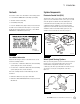
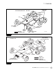
1 Introduction Contents System Components This manual contains service information for the following systems. Electronic Control Unit (ECU) 1 Introduction 앫 E version Meritor WABCO Anti-Lock Braking System (ABS) 앫 Automatic Traction Control (ATC) 앫 Roll Stability Control (RSC) 앫 Electronic Stability Controls (ESC) for trucks, tractors and buses The ABS version is marked on the ECU. Figure 1.1.
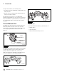
1 Introduction The type of axle determines sensor mounting location. Figure 1.6 앫 Steering axle sensors are installed in the steering knuckle or in a bolted-on bracket. 앫 Drive axle sensors are mounted in a block attached to the axle housing or in a bolted-on bracket. Check the wheel speed sensors for correct alignment and adjustment. Apply lubricant to the sensor and sensor clip whenever wheel-end maintenance is performed. Make sure tooth wheels are free of contaminants.
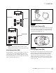
1 Introduction Figure 1.7 Figure 1.8 CAB 3 1 4M CHANNEL CURBSIDE SOLENOID VALVE (ACTIVE BRAKING VALVE) 2 CABLE 4007846a 4 Figure 1.8 Brake Pressure Sensor (BPS) CAB 4 The brake pressure sensor or BPS is part of the RSC, ESC and HSA system. It provides the system with the driver’s brake demand. The sensor can be located in the primary or secondary delivery circuit depending on the application. Figure 1.9. 1 6M CHANNEL Figure 1.9 CURBSIDE 2 5 3 6 1002006d Figure 1.
1 Introduction Off-Road ABS Switch Figure 1.10 On some vehicles, an off-road ABS switch can be included. The off-road ABS function improves vehicle control and helps reduce stopping distances in off-road conditions or on poor traction surfaces such as loose gravel, sand and dirt. ATC Switch 4006873a A vehicle manufacturer might offer an ATC switch to control the ATC function. Depending on the vehicle ECU configuration for the switch, there are two function options. 앫 Deep snow and mud option Figure 1.
1 Introduction Figure 1.12 WHEEL SPEED SENSORS 4S/4M CONFIGURATION — ABS ONLY ABS MODULATOR VALVES LAMPS ECU RELAY VALVE ABS MODULATOR VALVE WHEEL SPEED SENSORS QUICK RELEASE VALVE AIR LINES ELECTRICAL LINES ABS MODULATOR VALVE 1002004h Figure 1.12 Figure 1.13 VALVE PACKAGE INSTALLATION (REAR) 4S/4M ABS/ATC LAMPS ATC VALVE AIR LINES VALVE PACKAGE INSTALLATION (FRONT) LAMPS (UP TO THREE: ABS, TRAILER ABS, ATC) 1002004g Figure 1.
2 Stability and Safety Enhancement Systems ATC 2 Stability and Safety Enhancement Systems Automatic traction control is available as an option on all E version ECUs and is standard on most. ATC helps improve traction in low traction road conditions. ATC reduces the potential of jackknifing caused by excessive wheel spin during acceleration or in curves. ATC works automatically in two different ways.
2 Stability and Safety Enhancement Systems RSC Components Figure 2.3 RSC uses many of the same components used by ABS/ATC including modulator valves, active braking valves and wheel speed sensors. RSC ECUs are different from ABS ECUs as they contain an internal accelerometer that measures and updates the lateral acceleration of the vehicle and compares it to a critical threshold at which rollover may occur. Depending on the vehicle manufacturer, RSC ECUs have orientation on the XX/YY or ZZ axis.
2 Stability and Safety Enhancement Systems When operating the vehicle, always use safe driving techniques. The driver is always the most important factor in safe vehicle operation. Figure 2.5 Z ± 2° Y ± 2° +2° ± 90° DRIVING DIRECTION ZZ Orientation 4010607a Figure 2.5 Figure 2.6 0° ± 2° Z 0° ± 92° X DRIVING DIRECTION YY Orientation 4010608a Figure 2.
2 Stability and Safety Enhancement Systems Figure 2.7 4S/4M RSC/ATC (ALSO AVAILABLE IN 6S CONFIGURATIONS) TRAILER STABILITY CONTROL MODULATOR (OPTIONAL) TRACTOR PROTECTION VALVE VALVE PACKAGE INSTALLATION (REAR) TRAILER ACTIVE BRAKING VALVE LAMPS PRESSURE SENSOR (OPTIONAL) VALVE PACKAGE INSTALLATION (FRONT) FRONT AXLE ACTIVE BRAKING VALVE (OPTIONAL) ATC VALVE AIR LINES ELECTRICAL LINES 4007813a Figure 2.
2 Stability and Safety Enhancement Systems The ESC ECU contains parameter settings which are specific to a vehicle configuration validated by Meritor WABCO Engineering. It is imperative that the correct ECU is installed on your vehicle in service. Contact Meritor WABCO or your respective vehicle OEM with any questions regarding ESC ECU. Figure 2.8 and Figure 2.9. Figure 2.8 Z ± 5° -5° +2° Y -2° +2° X -2° 4010609a Figure 2.
2 Stability and Safety Enhancement Systems Figure 2.9 TRAILER STABILITY CONTROL MODULATOR (OPTIONAL) 4S/4M ESC/ATC (ALSO AVAILABLE IN 6S CONFIGURATIONS) TRACTOR PROTECTION VALVE VALVE PACKAGE INSTALLATION (REAR) TRAILER ACTIVE BRAKING VALVE ESC MODULE LAMPS PRESSURE SENSOR SAS ATC VALVE FRONT AXLE ACTIVE BRAKING VALVE AIR LINES ELECTRICAL LINES 4007814a Figure 2.
3 Diagnostics, Troubleshooting and Testing 앫 If the vehicle is equipped with ATC and RSC/ESC, when the ignition is turned to the ON position, the ABS and ATC/RSC/ESC will both light but the ATC/RSC/ESC lamp will stay lit briefly after the ABS lamp goes out. General 3 Diagnostics, Troubleshooting and Testing Maintenance Information There is no regularly scheduled maintenance required for the Meritor WABCO ABS, ATC, RSC or ESC systems. However, this does not change current vehicle maintenance requirements.
3 Diagnostics, Troubleshooting and Testing Ignition ON OFF Normal Operation ABS lamp comes on at ignition momentarily for a bulb check, then goes out. System is OK. After servicing ABS components ABS lamp does not go out at ignition. When vehicle is driven at speeds above 4 mph (6 km/h), lamp goes out. System is OK. Off-road ABS operation. Refer to the off-road ABS information in this section. ABS lamp flashes during vehicle operation.
3 Diagnostics, Troubleshooting and Testing NOTE: When switching between J1939 and J1708 communications, vehicle ignition must be cycled between sessions to correctly communicate with ECU. Figure 3.6 Figure 3.4 4010613a Figure 3.6 4010611a Figure 3.7 Figure 3.4 Figure 3.5 4010612a 4010614a Figure 3.5 Figure 3.7 4. 14 In the Main Menu, select J1939 Tractor ABS or J1708 TOOLBOX™, then Tractor ABS. The ABS Main Screen will appear. Figure 3.6 and Figure 3.7.
3 Diagnostics, Troubleshooting and Testing Double-clicking on the fault, or clicking on Details, will provide troubleshooting and detailed repair instructions. TOOLBOX™ Software version 11 also provides links to the appropriate system schematic which are also provided in this maintenance manual. Figure 3.8 NOTE: If you are using TOOLBOX™ Software version 11, Internet Explorer is required to load files containing repair information, maintenance manual and schematics.
3 Diagnostics, Troubleshooting and Testing Diagnostics: The process of using blink codes to determine ABS faults. If you do not receive eight flashes, there are still active faults that must be repaired before they can be cleared. Fault: An ABS malfunction detected and stored in memory by the Meritor WABCO ECU. System faults may be Active or Stored. NOTE: The clear mode is also used to disable the ATC function.
3 Diagnostics, Troubleshooting and Testing Table A: Troubleshooting with Blink Code Diagnostics Procedure System Response Action Diagnostics Mode Step I. Possible responses: Turn ignition ON. ABS indicator lamp comes on momentarily then goes out, indicating System OK. No recognizable active faults in the ABS. No action required. ABS indicator lamp does not light, indicating possible wiring fault or burned-out bulb. Inspect wiring. Inspect bulb. Make necessary repairs.
3 Diagnostics, Troubleshooting and Testing Blink Code Illustrations Figure 3.11 1 Second Hold Active Fault 1-8 Flashes 1-6 Flashes Pause Pause Pause Pause 1.5 s 1.5 s 4s 1.5 s Light ON 1st Digit 2nd Digit (2) (3) Continues until ignition is turned off Repeat of Blink Code (3) (2) Example: Blink Code 2-3: Fault in ABS modulator valve, right rear drive axle. 1 Second Hold Off Stored Faults Pause Pause Pause 1.5 s 1.5 s 4s Light ON 1st Digit 2nd Digit Pause 1.
3 Diagnostics, Troubleshooting and Testing Figure 3.12 Note: After faults are cleared and vehicle is started, ABS lamp will stay on until vehicle is driven over 4 mph (6 km/h). 3 Second Hold Faults Cleared Pause Pause Pause Pause Pause 1.
3 Diagnostics, Troubleshooting and Testing Condition Reason Action Eight flashes not received after blink code switch pressed for at least three seconds, then released. Active faults still exist. Identify active faults, then make necessary repairs. Turn ignition OFF, then repeat Blink Code Diagnostics.
3 Diagnostics, Troubleshooting and Testing Testing Wheel Speed Sensor Testing Sensor Adjustment 앫 Push the sensor in until it contacts the tooth wheel. 앫 Do not pry or push sensors with sharp objects. 앫 Sensors will self-adjust during wheel rotation. Electrical Checks 앫 Check wheel speed sensor by itself for resistance. 앫 Check ECU harness and sensor together for resistance. Figure 3.13 and Figure 3.14. 앫 Verify no change in resistance or open circuit between sensor by itself and through harness.
3 Diagnostics, Troubleshooting and Testing Figure 3.
3 Diagnostics, Troubleshooting and Testing NOTE: If resistance exceeds 9.0 ohm for 12V system (21.0 ohm for 24V system), verify the reading was not taken between the inlet and outlet. If the correct pins were tested, clean the electrical contacts at the modulator and retest. Figure 3.15 BAYONET-STYLE CONNECTOR EXHAUST SOLENOID (BLUE WIRE) INLET SOLENOID (BROWN WIRE) GROUND TERMINAL 4004022a Figure 3.15 Figure 3.
3 Diagnostics, Troubleshooting and Testing Figure 3.17 CAB MOUNT ECU’S: LOOKING INTO WIRE HARNESS CONNECTOR X2 X3 X4 X1 16 13 10 7 4 1 13 10 7 4 1 16 13 10 7 4 1 13 10 7 4 1 17 14 11 8 5 2 14 11 8 5 2 17 14 11 8 5 2 14 11 8 5 2 18 15 12 9 6 3 15 12 9 6 3 18 15 12 9 6 3 15 12 9 6 3 4007205a Figure 3.
3 Diagnostics, Troubleshooting and Testing Figure 3.
3 Diagnostics, Troubleshooting and Testing Modulator Valve Testing Available in Meritor WABCO TOOLBOX™ Software (PC Diagnostics) Figure 3.20 The ABS modulator valves as well as the trailer modulator valve can be cycled using Meritor WABCO TOOLBOX™ Software. To cycle the modulator valves, choose the option “Valves” from the “Component Tests” drop-down menu. Or, if you are using TOOLBOX™ Software version 11 or higher, from “Components”. Figure 3.19. Figure 3.19 4010619a Figure 3.20 Figure 3.
3 Diagnostics, Troubleshooting and Testing Active Braking Valves (ABV) Testing Electrical Checks 앫 Check ABV 3/2 solenoid by itself for resistance. 앫 Check ECU harness and ABV 3/2 solenoid together for resistance. Figure 3.22 and Figure 3.23. 앫 Verify no change in resistance or open circuit between ABV by itself and through harness. 앫 Check harness by itself for any shorts to battery and shorts to ground. 앫 Measurements should read as follows: Location Measurement ABV Supply to ABV Common 7.0-14.
3 Diagnostics, Troubleshooting and Testing Figure 3.
3 Diagnostics, Troubleshooting and Testing Figure 3.24 Figure 3.26 4010621a Figure 3.24 Figure 3.25 4010623a Figure 3.26 Figure 3.27 4010622a Figure 3.25 The valve selection screen will appear where you can choose to cycle Front Axle ABV, Rear Axle ABV or Trailer ABV individually. Figure 3.26 or Figure 3.27. Then, listen to ensure the correct valve is cycling. This is helpful in verifying correct operation, installation and wiring. 4010624a Figure 3.
3 Diagnostics, Troubleshooting and Testing NOTE: If you are using versions older than TOOLBOX™ Software version 11, to test the function of the Trailer ABV, choose “Trailer Brake Valve” or “E4.3 Trailer Brake Valve” from the “Component Tests” drop-down menu. Listen to ensure the correct valve is cycling. If you are unsure which test option to choose, please contact Meritor WABCO OnTrac and have your ECU part number available.
3 Diagnostics, Troubleshooting and Testing Figure 3.30 Figure 3.32 SAS UB GND ESC MODULE CAN L H GND FRAME ECU 4010628a Figure 3.32 ESC Module Testing 4010626a Electrical Checks For the following checks, all of the ECU connectors must be plugged in as well as the SAS. The ECU provides voltage, ground and CAN communication to ESC module. Figure 3.
3 Diagnostics, Troubleshooting and Testing Location Measurement ESC Module Circuit ECU Voltage Supply to Ground 8.0-16.
3 Diagnostics, Troubleshooting and Testing Contact the Meritor WABCO OnTrac Customer Service Center at 866-OnTrac1 (668-7221) to ensure ESC module mounting is in accordance with ECU parameters. Figure 3.37 ESC Information Available in Meritor WABCO TOOLBOX™ Software 11 or Higher ESC Information can be accessed through Meritor WABCO TOOLBOX™ Software 11 or higher under Components, ESC.
3 Diagnostics, Troubleshooting and Testing Location Measurement Figure 3.40 Meritor Wabco SAS terminating Approximately 180 ohms resistor CAN High Voltage 2.5-5.0V CAN Low Voltage 0.1-2.4V Voltage Supply to Ground 8.0-16.
3 Diagnostics, Troubleshooting and Testing 앫 Take measurements at the ECU harness pins. Figure 3.42 and Figure 3.43. ECU Power Supply Circuit Connector Cab-Mounted Measurements should read as follows: Location Measurement Supply Voltage, Battery to chassis Ground 9.0-16.0V for 12V system Supply Voltage, Ignition to chassis Ground 9.0-16.
3 Diagnostics, Troubleshooting and Testing Figure 3.44 CAB MOUNT ECU’S LOOKING INTO WIRE HARNESS CONNECTOR X1 13 10 7 4 1 14 11 8 5 2 15 12 9 6 3 4007373a Figure 3.44 Figure 3.45 FRAME MOUNT ECU WITHOUT ESC LOOKING INTO WIRE HARNESS CONNECTOR 6 5 7 8 X1-GRAY 4 3 2 9 10 11 FRAME MOUNT ECU WITH ESC LOOKING INTO WIRE HARNESS CONNECTOR X1-BLACK 4 3 2 1 6 5 12 12 11 10 9 18 17 16 15 14 13 8 1 7 4007374a Figure 3.
4 Component Replacement Hazard Alert Messages 4 Component Replacement Figure 4.1 SENSOR SPRING CLIP Read and observe all Warning and Caution hazard alert messages in this publication. They provide information that can help prevent serious personal injury, damage to components, or both. WARNING To prevent serious eye injury, always wear safe eye protection when you perform vehicle maintenance or service. Release all air from the air systems before you remove any components.
4 Component Replacement Installation Figure 4.2 1. Connect the sensor cable to the chassis harness. 2. Install the fasteners used to hold the sensor cable in place. 3. Apply a Meritor WABCO recommended lubricant to the sensor spring clip and sensor. 4. Install the sensor spring clip. Make sure the spring clip tabs are on the inboard side of the vehicle. 5. Push the sensor spring clip into the bushing in the steering knuckle until the clip stops. 6.
4 Component Replacement 3. Figure 4.4 PORT 2, AIR OUT PORT 1, AIR IN After any repair has been performed, cycle the ignition key and test drive the vehicle. Verify that the ABS indicator lamp operates correctly. Active Braking Valves (ABV) Removal Depending on the OEM specs and vehicle system configuration, ABVs may be located near the rear axle, front axle and in line with trailer service/control line. Consult the vehicle OEM for exact location of these valves. WARNING 6.
4 Component Replacement Checking the Trailer ABV Installation Figure 4.5 AIR LINES PORT 1, AIR SUPPLY PORT 2, AIR DISCHARGE VALVE CONTROL DO NOT OPEN PORT 3, TREADLE AIR LINE 1. Connect the blue glad hand to a 50 cu. in. (819 cu. cm) air tank. 2. Start the vehicle. 3. Fully charge the reservoirs with air. Shut off the vehicle. 4. Activate the valve using TOOLBOX™ Software; verify correct operation and no active codes. 5. Listen for air leaks at the valve. 6.
4 Component Replacement Figure 4.7 RELAY VALVE ABS MODULATOR VALVE DELIVERY PORTS 1/2" NPT DELIVERY PORTS 3/8" NPT CONTROL PORT 1/4" NPT SUPPLY PORT 1/2" NPT ABS RELAY VALVE PACKAGE ABS MODULATOR VALVE DELIVERY PORTS 1/2" NPT Carefully separate the ABS modulator valve(s) from the relay or quick release valve. 4. Remove and discard old O-rings. Lubricate replacement O-rings with the grease provided. 5. Plug any unused ports on the replacement valve(s). 6.
4 Component Replacement WARNING Figure 4.10 MOUNTING BOLTS 12-13 FT-LB (18-20 N•m) Relieve line pressure by bleeding the air from the appropriate supply tank. Pressurized air can cause serious personal injury. 4. Relieve line pressure by bleeding the air from the appropriate supply tank. 5. Disconnect the wiring from the solenoid valve. 6. Disconnect the supply air line from the adapter and the treadle air line from the solenoid valve. 7.
4 Component Replacement 4. Figure 4.12 ATC VALVE AND ADAPTER CONTROL PORT SUPPLY PORT Remove the mounting hardware. Remove the ECU. Figure 4.13. Figure 4.13 ABS VALVE PACKAGE UNIVERSAL ECU MOUNTING BOLTS 4-5 LB-FT (6-8 N•m) O-RING (INSTALLED) 1002045a FRAME-MOUNTED ECU BASIC ECU Figure 4.12 4003974a Figure 4.13 6. Connect the supply air line to the supply port on the adapter. 7. Connect the treadle air line to the control port on the solenoid valve.
4 Component Replacement 앫 Follow the ESC End of Line Calibration Procedure described in this manual. Figure 4.14 앫 When the ESC End of Line Calibration Procedure is completed, the ABS and ATC/ESC lamps should come on and go back off when ignition power is turned on. The ATC/ ESC lamp may remain on briefly after the ABS lamp goes off. 3. There should not be any active faults displayed in the ECU memory.
4 Component Replacement 2. 3. When the ESC End of Line Calibration Procedure is completed, the ABS and ATC/ESC lamps should come on and go back off when ignition power is turned on. The ATC/ESC lamp may remain on briefly after the ABS lamp goes off. Figure 4.16 Z ± 5° -5° There should not be any active faults displayed in the ECU memory. +2° Y -2° Electronic Stability Control (ESC) Module Removal WARNING Park the vehicle on a level surface. Block the wheels to prevent the vehicle from moving.
4 Component Replacement 1. Follow the ESC End of Line Calibration Procedure described in this manual. 2. When the ESC End of Line Calibration Procedure is completed, the ABS and ATC/ESC lamps should come on and go back off when ignition power is turned on. The ATC/ESC lamp may remain on briefly after the ABS lamp goes off. 3. There should not be any active faults displayed in the ECU memory. Figure 4.17 4006870a Brake Pressure Sensor Figure 4.17 Removal 6.
5 System Configurations System Configuration Layouts 5 System Configurations Figure 5.3 6S/6M ABS The most common configurations are shown in this section. Always refer back to the vehicle OEM for the correct configuration of your vehicle. Refer to Figure 5.1, Figure 5.2, Figure 5.3, Figure 5.4, Figure 5.5, Figure 5.6 and Figure 5.7 for system configuration layouts. VALVE PACKAGE INSTALLATION (REAR) LAMPS Figure 5.
5 System Configurations Figure 5.5 Figure 5.7 6S/4M ABS/ATC VALVE PACKAGE INSTALLATION (REAR) 4S/4M ESC/ATC (ALSO AVAILABLE IN 6S CONFIGURATIONS) TRACTOR PROTECTION VALVE TRAILER ACTIVE BRAKING VALVE LAMPS TRAILER STABILITY CONTROL MODULATOR (OPTIONAL) VALVE PACKAGE INSTALLATION (REAR) LAMPS ESC MODULE ATC VALVE VALVE PACKAGE INSTALLATION (FRONT) ATC VALVE SAS AIR LINES ELECTRICAL LINES 1003367e PRESSURE SENSOR Figure 5.5 AIR LINES ELECTRICAL LINES Figure 5.
6 Wiring Diagrams and Connectors ECU Connector Pin Assignments 6 Wiring Diagrams and Connectors Refer to Figure 6.1, Figure 6.2, Figure 6.3, Figure 6.4, Figure 6.5, Figure 6.6, Figure 6.7, Figure 6.8, Figure 6.9, Figure 6.10, Figure 6.11, Figure 6.12, Figure 6.13 and Figure 6.14 for ECU wiring diagrams. Figure 6.1 BASIC X2 X1 1 4 7 10 13 16 1 4 7 10 13 2 5 8 11 14 17 2 5 8 11 14 3 6 9 12 15 18 3 6 9 15 4004024b BASIC ECU (CAB-MOUNTED) Figure 6.1 Figure 6.
6 Wiring Diagrams and Connectors ECU (Frame-mounted) Figure 6.4 2 3 4 5 6 1 2 3 4 5 11 10 9 8 7 12 11 10 9 8 7 1 12 X4-BROWN (ONLY FOR 6 CHANNEL) 6 X2-BLACK X1-GRAY 3 4 5 6 1 2 3 4 5 10 9 8 7 12 11 10 9 8 6 2 11 7 1 12 X3-GREEN 4004026a FRAME-MOUNTED ECU Figure 6.4 ECU (Frame-mounted) with ESC and/or HSA Figure 6.
6 Wiring Diagrams and Connectors Basic ECU ABS Only with Optional Automatic Traction Control (ATC) (Cab-mounted) Figure 6.
6 Wiring Diagrams and Connectors 6S/6M Universal ECU ABS Only with Optional Automatic Traction Control (ATC) (6S/4M and 4S/4M Configurations are also available) Figure 6.
6 Wiring Diagrams and Connectors 6S/6M Universal ECU with Roll Stability Control (RSC) (6S/4M and 4S/4M Configurations are also available) Figure 6.
6 Wiring Diagrams and Connectors 6S/6M Universal ECU with RSC and Optional Front Axle Brake (6S/4M and 4S/4M Configurations are also available) Figure 6.
6 Wiring Diagrams and Connectors 6S/6M Universal ECU with Electronic Stability Control (ESC) (6S/4M and 4S/4M Configurations are also available) Figure 6.
6 Wiring Diagrams and Connectors 6S/6M Universal ECU with ESC and Hill Start Aid (HSA) (6S/4M and 4S/4M Configurations are also available) Figure 6.
6 Wiring Diagrams and Connectors 6S/6M Frame-mounted ECU ABS or RSC (6S/4M and 4S/4M Configurations are also available) Figure 6.
6 Wiring Diagrams and Connectors 6S/6M Frame-mounted ECU with ESC (6S/4M and 4S/4M Configurations are also available) Figure 6.
6 Wiring Diagrams and Connectors 6S/6M Frame-mounted ECU with ESC and Hill Start Aid (HSA) (6S/4M and 4S/4M with HSA and without ESC Configurations are also available) Figure 6.
60 SID 1 1 1 1 1 1 SPN 789 789 789 Meritor WABCO Maintenance Manual MM-0112 (Revised 05-13) 789 789 789 6 5 4 3 2 1 FMI 4+2 4+2 4+2 4+2 5+2 3+2 Blink Code ABS WL Shorted to Ground Short Circuit ABS WL ABS WL ABS WL Shorted to UBATT Open Circuit ABS WL ABS WL Warning Light Incorrect Tire Air Gap Description ESC/RSC/ATC/ HSA Disabled ABS Wheel Disabled ESC/RSC/ATC/ HSA Disabled ABS Wheel Disabled ESC/RSC/ATC/ HSA Disabled ABS Wheel Disabled ESC/RSC/ATC/ HSA Di
1 789 1 1 789 789 1 789 1 1 789 789 SID SPN 12 11 10 9 8 7 FMI 5+2 5+2 3+2 5+2 3+2 6+2 Blink Code ABS WL Frequency Too High ABS WL Speed Drop-Out ABS WL ABS WL Wires Mismatched Abnormal Speed (Chatter) ABS WL ABS WL Incorrect Tone Ring Excessive Slip Warning Light Description ESC/RSC/ATC/ HSA Disabled ABS Wheel Disabled ESC/RSC/ATC/ HSA Disabled ABS Wheel Disabled ESC/RSC/ATC/ HSA Disabled ABS Wheel Disabled ESC/RSC/ATC/ HSA Disabled ABS Wheel Disabled ESC/R
62 SID 2 2 2 2 2 2 SPN 790 790 790 Meritor WABCO Maintenance Manual MM-0112 (Revised 05-13) 790 790 790 6 5 4 3 2 1 FMI 4+1 4+2 4+1 4+1 5+1 3+1 Blink Code ABS WL Shorted to Ground Short Circuit ABS WL ABS WL ABS WL Shorted to UBATT Open Circuit ABS WL ABS WL Warning Light Incorrect Tire Air Gap Description ESC/RSC/ATC/ HSA Disabled ABS Wheel Disabled ESC/RSC/ATC/ HSA Disabled ABS Wheel Disabled ESC/RSC/ATC/ HSA Disabled ABS Wheel Disabled ESC/RSC/ATC/ HSA Di
2 790 2 2 790 790 2 790 2 2 790 790 SID SPN 12 11 10 9 8 7 FMI 5+1 5+1 3+1 5+1 3+1 6+1 Blink Code ABS WL Frequency Too High ABS WL Speed Drop-Out ABS WL ABS WL Wires Mismatched Abnormal Speed (Chatter) ABS WL ABS WL Incorrect Tone Ring Excessive Slip Warning Light Description ESC/RSC/ATC/ HSA Disabled ABS Wheel Disabled ESC/RSC/ATC/ HSA Disabled ABS Wheel Disabled ESC/RSC/ATC/ HSA Disabled ABS Wheel Disabled ESC/RSC/ATC/ HSA Disabled ABS Wheel Disabled ESC/R
64 SID 3 3 3 3 3 3 SPN 791 791 791 Meritor WABCO Maintenance Manual MM-0112 (Revised 05-13) 791 791 791 6 5 4 3 2 1 FMI 4+4 4+4 4+4 4+4 5+4 3+4 Blink Code ABS WL Shorted to Ground Short Circuit ABS WL ABS WL ABS WL Shorted to UBATT Open Circuit ABS WL ABS WL Warning Light Incorrect Tire Air Gap Description ESC/RSC/ATC/ HSA Disabled ABS Wheel Disabled ESC/RSC/ATC/ HSA Disabled ABS Wheel Disabled ESC/RSC/ATC/ HSA Disabled ABS Wheel Disabled ESC/RSC/ATC/ HSA Di
3 791 3 3 791 791 3 791 3 3 791 791 SID SPN 12 11 10 9 8 7 FMI 5+4 5+4 3+4 5+4 3+4 6+4 Blink Code ABS WL Frequency Too High ABS WL Speed Drop-Out ABS WL ABS WL Wires Mismatched Abnormal Speed (Chatter) ABS WL ABS WL Incorrect Tone Ring Excessive Slip Warning Light Description ESC/RSC/ATC/ HSA Disabled ABS Wheel Disabled ESC/RSC/ATC/ HSA Disabled ABS Wheel Disabled ESC/RSC/ATC/ HSA Disabled ABS Wheel Disabled ESC/RSC/ATC/ HSA Disabled ABS Wheel Disabled ESC/R
66 SID 4 4 4 4 4 4 SPN 792 792 792 Meritor WABCO Maintenance Manual MM-0112 (Revised 05-13) 792 792 792 6 5 4 3 2 1 FMI 4+3 4+3 4+3 4+3 5+3 3+3 Blink Code ABS WL Shorted to Ground Short Circuit ABS WL ABS WL ABS WL Shorted to UBATT Open Circuit ABS WL ABS WL Warning Light Incorrect Tire Air Gap Description ESC/RSC/ATC/ HSA Disabled ABS Wheel Disabled ESC/RSC/ATC/ HSA Disabled ABS Wheel Disabled ESC/RSC/ATC/ HSA Disabled ABS Wheel Disabled ESC/RSC/ATC/ HSA Di
4 792 4 4 792 792 4 792 4 4 792 792 SID SPN 12 11 10 9 8 7 FMI 5+3 5+3 3+3 5+3 3+3 6+3 Blink Code ABS WL Frequency Too High ABS WL Speed Drop-Out ABS WL ABS WL Wires Mismatched Abnormal Speed (Chatter) ABS WL ABS WL Incorrect Tone Ring Excessive Slip Warning Light Description ESC/RSC/ATC/ HSA Disabled ABS Wheel Disabled ESC/RSC/ATC/ HSA Disabled ABS Wheel Disabled ESC/RSC/ATC/ HSA Disabled ABS Wheel Disabled ESC/RSC/ATC/ HSA Disabled ABS Wheel Disabled ESC/R
68 SID 5 5 5 5 5 5 SPN 793 793 793 Meritor WABCO Maintenance Manual MM-0112 (Revised 05-13) 793 793 793 6 5 4 3 2 1 FMI 4+6 4+6 4+6 4+6 5+6 3+6 Blink Code ABS WL Shorted to Ground Short Circuit ABS WL ABS WL ABS WL Shorted to UBATT Open Circuit ABS WL ABS WL Warning Light Incorrect Tire Air Gap Description ESC/RSC/ATC/ HSA Disabled ABS Wheel Disabled ESC/RSC/ATC/ HSA Disabled ABS Wheel Disabled ESC/RSC/ATC/ HSA Disabled ABS Wheel Disabled ESC/RSC/ATC/ HSA Di
5 793 5 5 793 793 5 793 5 5 793 793 SID SPN 12 11 10 9 8 7 FMI 5+6 5+6 3+6 5+6 3+6 6+6 Blink Code ABS WL Frequency Too High ABS WL Speed Drop-Out ABS WL ABS WL Wires Mismatched Abnormal Speed (Chatter) ABS WL ABS WL Incorrect Tone Ring Excessive Slip Warning Light Description ESC/RSC/ATC/ HSA Disabled ABS Wheel Disabled ESC/RSC/ATC/ HSA Disabled ABS Wheel Disabled ESC/RSC/ATC/ HSA Disabled ABS Wheel Disabled ESC/RSC/ATC/ HSA Disabled ABS Wheel Disabled ESC/R
70 SID 6 6 6 6 6 6 SPN 794 794 794 Meritor WABCO Maintenance Manual MM-0112 (Revised 05-13) 794 794 794 6 5 4 3 2 1 FMI 4+5 4+5 4+5 4+5 5+5 3+5 Blink Code ABS WL Shorted to Ground Short Circuit ABS WL ABS WL ABS WL Shorted to UBATT Open Circuit ABS WL ABS WL Warning Light Incorrect Tire Air Gap Description ESC/RSC/ATC/ HSA Disabled ABS Wheel Disabled ESC/RSC/ATC/ HSA Disabled ABS Wheel Disabled ESC/RSC/ATC/ HSA Disabled ABS Wheel Disabled ESC/RSC/ATC/ HSA Di
6 794 6 6 794 794 6 794 6 6 794 794 SID SPN 12 11 10 9 8 7 FMI 5+5 5+5 3+5 5+5 3+5 6+5 Blink Code ABS WL Frequency Too High ABS WL Speed Drop-Out ABS WL ABS WL Wires Mismatched Abnormal Speed (Chatter) ABS WL ABS WL Incorrect Tone Ring Excessive Slip Warning Light Description ESC/RSC/ATC/ HSA Disabled ABS Wheel Disabled ESC/RSC/ATC/ HSA Disabled ABS Wheel Disabled ESC/RSC/ATC/ HSA Disabled ABS Wheel Disabled ESC/RSC/ATC/ HSA Disabled ABS Wheel Disabled ESC/R
72 SID 7 7 7 8 8 8 SPN 795 795 795 Meritor WABCO Maintenance Manual MM-0112 (Revised 05-13) 796 796 796 6 5 3 6 5 3 FMI 2+1 2+1 2+1 2+2 2+2 2+2 Blink Code ABS WL Shorted to Ground ABS WL Shorted to UBATT ABS WL ABS WL Shorted to Ground Open Circuit ABS WL ABS WL Shorted to UBATT Open Circuit Warning Light Description Cause Action • Verify valve resistance of 4.0-9.0 ohm between IV to ground and OV to ground for 12v system (11.0-21.0 ohms for 24v system).
10 10 798 9 797 798 9 797 10 9 797 798 SID SPN 6 5 3 6 5 3 FMI 2+3 2+3 2+3 2+4 2+4 2+4 Blink Code ABS WL Shorted to Ground ABS WL Shorted to UBATT ABS WL ABS WL Shorted to Ground Open Circuit ABS WL ABS WL Shorted to UBATT Open Circuit Warning Light Description Cause Action • Verify valve resistance of 4.0-9.0 ohm between IV to ground and OV to ground for 12v system (11.0-21.0 ohms for 24v system).
74 SID 11 11 11 12 12 12 SPN 799 799 799 Meritor WABCO Maintenance Manual MM-0112 (Revised 05-13) 800 800 800 6 5 3 6 5 3 FMI 2+5 2+5 2+5 2+6 2+6 2+6 Blink Code ABS WL Shorted to Ground ABS WL Shorted to UBATT ABS WL ABS WL Shorted to Ground Open Circuit ABS WL ABS WL Shorted to UBATT Open Circuit Warning Light Description Cause Action • Verify valve resistance of 4.0-9.0 ohm between IV to ground and OV to ground for 12v system (11.0-21.0 ohms for 24v system).
15 803 14 802 14 13 801 802 13 801 14 13 801 802 SID SPN 3 7 5 4 6 5 3 FMI 8+5 8+3 8+5 8+1 7+3 7+3 7+3 Blink Code ABS WL ABS WL ABS WL Internal Voltage SUpply All ABVs Output Shorted to UBATT ABS WL (while supply voltage is detected as too low) ESC/RSC/ATC Disabled ESC/RSC/ATC/ HSA Disabled ABS Wheel Disabled ESC/RSC/ATC/ HSA Disabled ABS Wheel Disabled ESC/RSC/ATC/ HSA Disabled ABS Wheel Disabled • Measure the battery or ignition voltage supply.
76 SID 15 15 15 15 16 16 18 SPN 803 803 803 803 Meritor WABCO Maintenance Manual MM-0112 (Revised 05-13) 1045 1045 806 3 5 3 7 6 5 4 FMI 7+2 7+7 7+7 8+3 8+5 8+5 8+1 Blink Code Warning Light ABS WL (while supply voltage is detected as too low) ABS WL ABS WL ABS WL ABS WL ABS WL ABS WL Description ECU Voltage is too Low All ABVs High impedance All ABVs Shorted to ground Internal Voltage Supply E401 and E404 version only.
SID 18 18 19 19 19 19 19 19 SPN 806 806 807 807 807 807 807 807 6 5 4 3 2 1 6 5 FMI 7+6 7+6 7+6 7+6 7+6 7+6 7+2 7+2 Blink Code Warning Light ABS WL ABS WL ABS WL ABS WL ABS WL ABS WL ABS WL ABS WL Description ABV Drive Axle. Open Circuit ABV Drive Axle. Shorted to Ground ABV Front Axle. Shorted to UBATT ABV Front Axle. Open Circuit ABV Trailer Control. Shorted to UBATT ABV Front Axle. Shorted to Ground ABV Trailer Control.
78 SID 19 19 19 19 19 19 22 22 SPN 807 807 807 807 Meritor WABCO Maintenance Manual MM-0112 (Revised 05-13) 807 807 810 810 14 8 12 11 10 9 8 7 FMI 3+7 7+1 8+6 8+6 N/A 7+6 7+6 7+6 Blink Code ESC/RSC Disabled ABS/ESC/RSC/ ATC/HSA Disabled ABS WL ABS WL ABS WL ABS WL ABS WL ABS WL ABS WL (Only at start up) ABS WL Aux 1, 2, 3 or 4. Open Circuit Aux 1, 2, 3 or 4. Shorted to Ground SAS & ESC Module supply line. Shorted to UBATT SAS & ESC Module supply line.
88 88 520210 79 1069 520210 55 1045 88 55 1045 520210 55 1045 94 23 811 2622 SID SPN 5 2 1 2 1 7 5 3 5 FMI 7+1 8+6 N/A 7+1 7+8 7+7 7+7 7+7 7+4 Blink Code ATC WL ATC WL ESC System Configuration ESC CAN Datalink Fault ATC WL if Parameter is set Tire Pressure Monitor (TPM) ATC WL Blinking ABS WL CAN BLS (Brake light Switch) signal faulty ESC Initialization Not Complete N/A ABS WL Pressure Sensor shorted to ground HSA WL RSC Disabled ABS WL Pressure Sensor
80 SID 88 88 88 88 89 89 89 89 89 SPN 520210 520210 520210 520210 Meritor WABCO Maintenance Manual MM-0112 (Revised 05-13) 1807 1807 1807 1807 1807 12 8 7 2 1 14 13 12 9 FMI 8+6 7+1 8+6 8+6 8+6 8+6 8+6 8+6 7+1 Blink Code ATC WL ATC WL ATC WL ATC WL ATC WL ATC WL ATC WL ESC System Failure ESC Initialization required ESC Module Mounting Fault SAS Offset Fault SAS Not Plausible Steering Ratio Fault SAS Calibration Fault ATC WL ATC WL ESC CAN messages mis
231 639 231 231 639 639 231 639 231 231 639 639 89 1807 231 89 1807 639 SID SPN 13 12 10 9 6 5 2 14 13 FMI 7+1 7+1 7+1 7+1 7+1 7+1 7+1 8+6 8+6 Blink Code ATC WL SAS Internal Fault Temporary ABS WL ABS WL Temporary ABS WL SAE J1939 Internal Error SAE J1939 XBR Timeout ABS WL SAE J1939 Data Link EEC1 Timeout SAE J1939 XBR Timeout ABS WL SAE J1939 No Access ABS WL ABS WL ATC WL SAS not Calibrated SAE J1939 Data Link VSC1 speed erratic, intermittent or inc
82 SID 231 251 253 253 253 253 SPN 639 627 630 Meritor WABCO Maintenance Manual MM-0112 (Revised 05-13) 630 630 630 14 13 12 2 3 14 FMI 8+6 8+4 8+4 8+2 8+2 7+1 Blink Code ABS WL ABS WL ABS WL ABS WL ATC WL Incorrect ABS System Configuration.
254 254 629 254 629 629 254 629 254 254 629 629 SID SPN 14 13 12 9 8 5 FMI 8+6 8+6 8+3 2+1 7+1 8+4 Blink Code ABS WL ABS WL ABS WL Accelerometer Out of Range ECU Mounting, Accelerometer Not Plausible ABS WL Excessive Modulator Activation Time Internal Error ABS WL ABS WL No Loads Detected Excessive Slip Warning Light Description RSC Disabled RSC Disabled ESC/RSC/ATC/ HSA Disabled ABS Wheel Disabled ESC/RSC Disabled ATC Disabled if Fault on Driven Wheel ABS Whee
8 Appendix I Reconfiguration Procedure 8 Appendix I Figure 8.1 How to Reconfigure an ECU (E Version) Before reconfiguring the ECU, contact the Meritor WABCO OnTrac Customer Service Center at 866-668-7221 for additional information. E version ECUs will automatically learn and memorize the following components if they are connected at start up: 앫 ATC valve 4010669a Figure 8.1 앫 Retarder relay or third brake relay 앫 Datalink SAE J1939 Figure 8.
8 Appendix I NOTE: Vehicle Ignition must be cycled and vehicle test driven over 4 mph (6.4 kph) to complete reset memorization. Manual Reconfiguration Refer to Table C and Figure 8.4 for information on manual reconfiguration. Table C Action Result Reason 1. Turn the ignition ON. 2. Press and hold the blink switch for at least three seconds. The ABS lamp displays the ABS system configuration code: Stored faults cleared, no active faults present. Continue with reconfiguration.
8 Appendix I Figure 8.4 A system reconfiguration is illustrated below: IGNITION ON -1s -1s -1s SWITCH 3 Second Hold -1s -1s ATC Reset Confirmation Pause Pause Pause Pause Pause Pause Pause 1.5 s 4s 4s 4s 4s 4s 4s System ID (2) System ID (2) System ID (2) System ID (2) System ID (2) Continues until power is turned off System ID (2) ATC ATC Lamp — Dyno Function (remains lit for entire test) Light ON* *ATC Lamp will light only if ATC is connected. Figure 8.
9 Appendix II ESC End of Line Calibration Procedure 9 Appendix II Figure 9.1 This procedure is performed as part of the final assembly of the vehicle at the manufacturing site. Also, this procedure must be performed in the field by a trained technician if components are replaced such as the Steering Angle Sensor (SAS), the Electronic Stability Control (ESC) module or the ESC Electronic Control Unit (ECU).
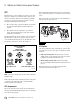
9 Appendix II Figure 9.3 Figure 9.5 4010689a Figure 9.5 Figure 9.6 4010672a Figure 9.3 Figure 9.4 4010674a Figure 9.6 Figure 9.7 4010673a Figure 9.4 To access the ESC EOL: 앫 From the bar menu at the initial screen, click on the “ESC Menu” button. A drop-down box will appear. Select the option “End of Line.” Figure 9.5. 앫 If you are using TOOLBOX™ Software version 11 or higher, click on “Components” button. A drop box will appear, Select “ESC” then select “Start EOL”. Figure 9.6 and Figure 9.7.
9 Appendix II In the message box that appears, click the “SAS Calibration” button. Figure 9.8. Figure 9.10 Figure 9.8 4010676a Figure 9.8 NOTE: If SAS has NOT been replaced but vehicle has had an alignment performed or other steering components have been replaced, it is necessary to recalibrate SAS regardless of current calibration. Figure 9.9 may appear if unit has had SAS calibrate at some point. Click on Yes to recalibrate SAS. Figure 9.10. 4010678a Figure 9.
9 Appendix II The SAS calibration is now completed. The ATC lamp will blink continuously to inform driver ECU is in learning mode. ESC Initialization Tip: Carefully follow the instructions that appear in the message box. Figure 9.13. Once the ESC initialization is started, the messages will automatically change as the requirements are met. DO NOT click the “continue” button again as this may cause the process to fail. The ESC Initialization procedure requires the vehicle to be driven.
9 Appendix II Figure 9.15 Figure 9.16 4010683a Figure 9.15 Tip: The vehicle MUST come to a complete stop before starting the steering ratio calculation and turning the steering wheel 360 degrees for the first time. Once steering wheel is turned one revolution in either direction (360 degrees) accelerate slowly until 12 mph (19 kph) is reached. Continue driving in a circle until the screen automatically changes to inform the steering ratio is being calculated.
9 Appendix II Figure 9.17 Figure 9.18 4010686a 4010685a Figure 9.18 Figure 9.17 With the vehicle stopped, ESC End of Line Data with the Steering Ratios and Steering Angle Offset values will appear. The data can be saved or printed for maintenance records. If saving or printing is not desired, click “Close”. The next screen will automatically appear to complete the ESC initialization. Figure 9.18. For the ECU to be able to save ratios and ESC EOL data, the ignition MUST be cycled.
9 Appendix II Figure 9.19 4010687a Figure 9.19 Figure 9.20 4010688a Figure 9.20 The ESC EOL Initialization procedure is completed. NOTE: If ESC EOL initialization was not properly completed and/or ratios correctly saved, code SID 88 FMI 1 will be active. Follow the ESC initialization again and make sure each portion is successfully completed. Make sure ignition power down is completed for the ECU to successfully save data.
Meritor WABCO Vehicle Control Systems 2135 West Maple Road Troy, MI 48084-7121 866-OnTrac1 (668-7221) Copyright 2013 meritorwabco.com Meritor, Inc.