Air Brake Handbook | Compressors | Valves | Wheel End Solutions | Air Treatment | Integrated Modules | Electronics | ®
©2009 Bendix Commercial Vehicle Systems LLC • All Rights Reserved
The Air Brake Handbook ©2009 Bendix Commercial Vehicle Systems LLC • All Rights Reserved More info: visit www.bendix.
Device Index Alphabetic Device Index A-18™ Controller Assy. . . . . . . 42 Actuators . . . . . . . . . . . . . 17 AD-2® Air Dryer. . . . . . . . . . 12 AD-4® Air Dryer. . . . . . . . . . 12 AD-9® Air Dryer. . . . . . . . . . 12 AD-IP® Air Dryer . . . . . . . . . 12 AD-IS® Air Dryer Module . . . . . 12 AD-SP® Air Dryer . . . . . . . . . 13 AF-3™ In-line Air Filter . . . . . . 13 Air Disc Brakes . . . . . . . . . . 20 ASA-5® Automatic Slack Adjuster 18 BA-921® Air Compressor . . . .
Handbook Section Index How to use the Air Brake Handbook This nine-section handbook provides an introduction to the use and operation of Bendix air brake systems and devices. Components are introduced and shown with typical system diagrams to show where they are used. As new components are introduced and their function explained, they gradually build up to a complete functioning air brake system. Partial system-drawings, throughout the manual, assist in explaining of the use of the components.
General Precautions IMPORTANT The systems presented in this manual are intended for illustrative purposes only and are not intended to be used for actual vehicle piping. Air Brake System General Precautions WARNING! PLEASE READ AND FOLLOW THESE INSTRUCTIONS TO AVOID PERSONAL INJURY OR DEATH: When working on or around a vehicle, the following general precautions should be observed at all times. 1. Park the vehicle on a level surface, apply the parking brakes, and always block the wheels.
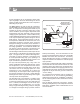
Introduction Section 1: An Overview Air Supply The vehicle’s compressor takes in filtered air, either at atmospheric pressure from the outside or already at an increased pressure (e.g. from the engine turbocharger), and compresses it. The compressed air is delivered to the air dryer where water and a small amount of oil is removed.
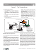
Overview Section 2: The Charging System • The charging system consists of: • • • • An air compressor, to pressurize the system A governor, to control when the compressor needs to build, or stop building, air for the system and also to control the air dryer purge cycle An air dryer, to remove water and oil droplets from the air Reservoirs (or “air tanks”) to store air to be used for vehicle braking, etc.
Compressors As the atmospheric air is compressed, all the water vapor originally in the air is carried along into the air system (as well as a small amount of the compressor lubricating oil) as vapor. The Duty Cycle is the ratio of time the compressor spends building air, relative to the total engine running time. Air compressors are designed to build air (run “loaded”) up to 25% of the time.
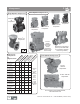
Compressors Single-Cylinder Compressors Two-Cylinder Compressors BX-2150™ air compressor Tu-Flo® 700 air compressor Tu-Flo® 501 air compressor Tu-Flo® 500 air compressor Tu-Flo® 400 air compressor BA-921® air compressor BA-922® air compressor (shown) or DuraFlo 596™ air compressor (exterior view is very similar) Four-Cylinder Compressors D Compressor Comparison by Displacement is p at lac 12 em 50 e n C 0R tC yl F P in de M M r lu En s br g ic in at e ed / s e co W ava lfol at i ed er l.
Compressor Maintenance Guidelines Maintenance Schedule and Usage Guidelines 2 Discharge Line Length Regularly scheduled maintenance is the single most important factor in maintaining the air brake charging system. The table below is an introduction to the maintenance intervals for air brake charging systems. See your compressor and/or air dryer Service Data sheet for more information. If you are concerned that a compressor may be passing oil, use the Bendix® BASIC Test Kit: Order Bendix P/N 5013711.
Governors and Components Governors and Components The Governor monitors the air pressure in the supply reservoir and operates the compressor unloading mechanism to control whether the compressor builds air pressure or not. The Bendix® D-2® governor is an adjustable pistontype valve available preset to a choice of pressure settings. Note: The pressure range between the cutin and cut-out pressure is designed into the governor and is not adjustable.
Reservoirs and Components Reservoirs (or “air tanks”) serve the air brake system as a storage tank for compressed air. The reservoir size is selected by the vehicle manufacturer to provide an adequate amount of air for use by the braking system and other control devices. Bendix reservoirs are built in accordance with SAE specifications and are available in various sizes in both single and double compartment design configurations, and are certified to comply with government regulations (such as FMVSS 121).
Air Dryers Air Dryers The air dryer is an in-line filtration system that removes both water vapor and oil droplets from the compressor discharge air after it leaves the compressor. This results in cleaner, drier air being supplied to the air brake system, and aids in the prevention of air line and component freeze-ups in winter weather. Air dryers typically use a replaceable cartridge containing a desiccant material and an oil separator.
Air Dryers and Filters AD-SP® Air Dryer (installation uses SC-PR™ valve) SC-PR™ Valve The AD-SP® air dryer uses a small amount of air from the supply and front axle (secondary) reservoirs to perform the purge function. Because of this difference, the AD-SP® air dryer is smaller and lighter than air dryers that have their purge volume within the dryer canister. An SC-PR™ Single Check Protection Valve is used in conjunction with the AD-SP™ air dryer.
Additional Charging System Related Components A double check valve is used in the air system when a single function or component must receive air from, or be controlled by, the higher of two sources of pressure. An internal disc or shuttle moves in response to the higher air pressure and allows that air source to flow out of the delivery port. It is recommended that double check valves be mounted so that the shuttle (or disc) operates horizontally.
Dual Circuit Brake Valves Section 3: The Control System The control system typically consists of: • A foot brake valve and often an additional hand- • Vehicle parking using push-pull hand operated operated trailer brake control valve valves and spring brakes, • Brake actuators or rotochambers, to change the • Anti-compounding system design to prevent both applied air pressure into a push-rod force which operates the foundation brakes (air disc, S-Cam, etc.
Dual Circuit Brake Valves, continued Secondary Delivery to Trailer Brakes Brake Chamber Primary Delivery to Trailer Brakes Brake Valve Supply from Primary Reservoir Modulator Delivery to Front Brakes May Use QR-1® Valve Delivery to Rear Brakes Modulator (See ABS section for more about modulators) Mostly used in the transit (buses/coaches) industry, the E-10PR™ retarder control brake valve has circuitry that is used to communicate with retarder systems installed on automatic transmission vehicles - e
Actuators Actuators Brake Chamber Actuators convert the air pressure being applied into a mechanical push-rod force acting on the foundation brakes. Air enters the actuator and pressurizes a chamber containing a rubber diaphragm. The air pushes against the diaphragm, pushing against the return spring and moving the push-plate (and pushrod) forward.
Slack Adjusters Slack Adjusters The slack adjuster is the link between a brake chamber or actuator and the S-Cam brake camshaft. Its arm is fastened to the push rod with a yoke and its spline is installed on the foundation brake cam shaft. It transforms and multiplies the force developed by the chamber into a torque which applies the brakes via the brake camshaft.
Foundation Brakes Spider Brake Chamber Automatic Slack Adjuster Axle Brake Drum CAM Shoe S-CAM BRAKE Friction Material Foundation Brakes: S-Cam and Air Disc The foundation brake is the actual braking mechanism located at each end of the axle that provides the primary retardation for controlling vehicle speeds. It generally consists of an air service and/or spring brake chamber, a mechanical brake mechanism and friction material.
Foundation Brakes, continued a “premium” material designed for high heat situations instead of a “standard” material designed for lighter duty operations. Brake Block Brake Lining AIR DISC BRAKE Rotor Brake Chamber Air Disc Brakes Bendix air disc brakes are a “floating caliper” design for use as a foundation brake on all axles of heavy commercial vehicles and trailers. In terms of performance and ease of service, Bendix air disc brakes compared favorably to traditional S-Cam brakes.
Quick Release, Ratio Valves Quick R elease Valves The function of the quick release valve is to speed up the exhaust of air from the air chambers. It is mounted close to the chambers it serves. In its standard configuration, the valve is designed to deliver within one psi of control pressure to the controlled device; however, for special applications the valve is available with greater differential pressure designed into the valve.
Ratio, Proportioning Valves Bobtail R atio Valves The LQ-5™ bobtail ratio valve is used on the front (steering) axle of tractor air brake systems to reduce brake application pressure during normal tractor-trailer operation. During bobtail mode (when the tractor is not pulling a trailer), tractor braking performance is improved because the LQ-5™ bobtail ratio valve delivers full brake pressure to the steering axle.
Relay Valves Relay Valves Relay valves are primarily used on vehicles to apply and release rear axle(s) service or parking brakes. When the driver applies the brakes, air travels through the delivery (in this case signal) line to the relay valve and moves an internal piston down. This closes the exhaust and opens the delivery of air to the brakes.
Push-Pull Valves Push-Pull Cont rol Valves Push-pull control valves are most often mounted on the vehicle dash board and are used for a variety of control applications. The PP-1® and PP-2™ valves are pressure sensitive, normally closed, on/off control valves which automatically return to the exhaust (button out) position when supply pressure is below the required minimum. They may be manually operated to either position when pressure is above the required minimum.
Spring Brake Valves Spring Bra ke Valves The SR-1™ spring brake valve is used in dual circuit brake systems and serves two functions; during normal operation, it limits hold-off pressure to the spring brakes to 90 or 95 psi. If a loss of pressure occurs in the rear brake service supply, the valve will provide a modulated spring brake application, proportional to the driver’s service braking pressure delivered to the front axle.
Lever Operated Control Valves Lever Operated Control Valves The TW-2 ™ and TH-3 ™ valves are identical in appearance (and similar to the TW-1™, TW-3™ and TW-4™) except they have two control valves housed in a single body. These two valves differ by the internal cammed control lever, which for the TW-2™ control valve has two lever positions, while the TH-3™ valve has three.
Additional Control Valves Additional Cont rol Valves Inversion valves are air operated control valves, and unlike most control valves are normally open, i.e. without control pressure the supply is common to the delivery. The inversion valve is closed by using air pressure from another source and is primarily used in emergency or parking brake systems which operate with air from an isolated reservoir.
Tractor/Trailer Parking and Emergency Systems Section 4: Tractor Parking, Trailer Charging/Parking and Emergency Systems The tractor/trailer parking and emergency system typically consists of: • The tractor parking control system • The trailer parking and emergency system, and • The tractor protection system See the front covers of this handbook for system schematics.
Dash Control Modules The MV-3 ® dash control module combines the functions of a PP-1® control valve and a PP-7™ trailer supply valve together into a unified device. Tractor Service Reservoir #1 Exhaust Port Supply #1 Auxiliary Delivery Port Delivery The Bendix® MV-3® dash control module is a twobutton, push-pull control valve housed in a single body which includes a dual circuit supply valve and a check valve.
Tractor P rotection Valves Tractor Pr otection Valves The primary function of tractor protection valves (e.g. the TP-3® tractor protection valve) is to protect the tractor air brake system under trailer breakaway conditions and/or conditions where severe air leakage develops in the tractor or trailer. In addition, in everyday use, the valve is used to shut off the trailer service and supply lines before disconnecting the tractor from the trailer.
Trailer Spring Brake Valves Trailer Spring Brake Valves SR-2™ Spring Brake Valve Trailer spring brake valves are designed for use in trailer air brake systems. The SR-4™ trailer spring brake valve was an earlier design that used a dedicated spring brake reservoir for release of the trailer spring brakes. Note: This valve is available for service only, due to changes made in FMVSS 121 (superseded by SR-5™). All other Bendix spring brake valves use service reservoir air for trailer spring brake release.
Trailer Spring Brake Valves, continued The Bendix® SRC-7000™ trailer spring brake valve is a reservoir-mounted trailer valve that can control up to six spring brake actuators during parking or emergency applications. It has the following capabilities: • Automatically applies trailer spring brakes in the event of a breakaway or trailer supply line failure. • Protects trailer reservoir(s) air pressure in the event of a breakaway or trailer supply line failure.
Trailer/Converter Dolly Brakes Section 5: Converter Dolly Brakes Typical components found in a converter dolly brake system are shown in this section. See the cover pages for other system schematics. R-8P™ or R-12P™ Relay Valve System Schematic without ABS. (ABS currently required for most applications.
Trailer/Converter Dolly Brakes Typical Converter Dolly Components The R-8P™ and R-12P™ pilot relay valves are special purpose relays designed specifically for use on trailers and converter dollies. These 0 p.s.i. crack and differential relays speed up brake application signals to provide an equal or balanced pressure signal to all trailer and dolly brakes on double and triple trailer combinations.
Antilock Braking Systems Section 6: Antilock Braking Systems For color schematics of tractors and trucks see the fold-out covers of this handbook. Bendix® Antilock Braking Systems (ABS) use wheel speed sensors, ABS pressure modulator valves, and an Electronic Control Unit (ECU) to control either four or six wheels of a vehicle.
ABS Components Continued; Truck and Tractor ABS Operation ABS Components continued ... • • • Dash-mounted tractor ABS Indicator Lamp Service brake relay valve Dash-mounted trailer ABS Indicator Lamp (used on all towing vehicles manufactured after March 1, 2001) • Optional blink code activation switch • Optional ABS off-road switch.
Truck and Tractor ABS Operation; ATC Right Steer Axle Right Drive Right Additional Axle Axle Driver Bendix Premium ECUs have an optional ABS off-road control mode that more effectively accommodates these soft road conditions and shortens stopping distances while maintaining optimal vehicle steerability and stability.
Advanced ABS Advanced ABS YawS tability Yaw stability counteracts the tendency of a vehicle to spin about its vertical axis. During operation, if the friction at the tires is not sufficient to oppose lateral (side) forces, one or more of the tires can slide, causing the truck/tractor to spin. These are referred to as under-steer or over-steer situations.
Advanced ABS Operation, Features Steering Angle Sensors The sensor enables the Bendix Advanced stability system to capture the driver’s steering input and intervene if a yaw correction is indicated. The sensor also provides the earliest indication of an increase in lateral acceleration leading to a potential roll event, resulting in much higher stability margin when a vehicle is equipped with a steering angle sensor.
Advanced ABS Features Stability System Effectiveness ESP® Stability System Sense Potential Situations Quickly and Completely Speed Measures the vehicle's velocity Lateral Acceleration Measures the vehicle's tendency to roll Steering Captures the driver's intended direction Brake Demand Accurately supplements the driver Yaw Rate Measures vehicle spin, and compares it to the steering intention and expected rate of turn Reaction Time and Robustness Multi-Level Sensing Tuning Leading indicators aid
Trailer ABS Components and Operation Trailer ABS Co mponents Typical Trailer ABS components are: • Bendix Electronic Control Units (ECUs) such as: □ the TABS-6 standard trailer ABS module, □ the TABS-6 Advanced (a single channel ABS trailer system) with roll stability control □ the TABS-6 Advanced MC (a multi-channel version of the advanced trailer ABS system) □ as well as former Bendix models including the MC-30™, A-18™ controllers shown on this page.
Trailer ABS Operation and Features, PLC,Troubleshooting Example of 2S/1M Axle Control ABS Trailer Schematic Right “Curb-Side” A Brake Light Power B Ignition Power C NC D Indicator Lamp E Ground ASA-5® Automatic Slack Adjuster SB-4™ Spring Brake Control Line Trailer Chassis Harness 7-Pin Connector 5-Pin Connector Trailer ABS Pigtail Harness SR-5™ Trailer Spring Brake Valve Ground Supply Line Ignition Power WS Sensor “SR” Cyclone DuraDrain™ Filtration Units TABS-6 Trailer ABS Module MOD1 Brake Li
Advanced Trailer ABS Operation and Features, Example of Advanced 4S/2M ABS Trailer Schematic Ignition Power 7-Pin J560 Connector Right “Curb-Side” A Brake Light Power B Ignition Power C NC D Indicator Lamp E Ground Ground Brake Light Power “S-F” Air Suspension Bellows “S-D” Bendix® WS-24™ Wheel Speed Sensors ASA-5® Automatic Slack Adjusters 5-Pin Connector Trailer ABS Trailer Pigtail Harness Chassis Harness Multi Channel Bendix® TABS-6 Advanced Trailer ABS Module Control Line Supply Line Bendi
Troubleshooting ABS Troubleshooting Truck, Tractor and Trailer ABS Bendix ECU controllers contain self-testing diagnostic circuitry that continuously checks for the normal operation of internal components and circuitry, as well as external ABS components and wiring. See the Service Data Sheet for the ABS controller for full troubleshooting information. Diagnostic Trouble Codes: General When an erroneous system condition is detected, the ECU controllers: 1.
Troubleshooting ABS Bendix® ACom™ Diagnostics Software Bendix ® ACom ™ Diagnostics tool is a PC-based software program and is designed to meet RP-1210 industry standards. This software provides the technician with access to all the available ECU diagnostic information and configuration capability, including: ECU information, diagnostic trouble codes and repair information, configuration (ABS, ATC, and more), wheel speed information, etc.
Additional Systems and Components Section 7: Additional Systems and Components Bendix supplies many other products and systems used on commercial vehicles. Advanced Technologies Adaptive Cruise with Braking Bendix® Wingman™ ACB - Active Cruise with Braking is a unique approach to adaptive cruise control technology.
Additional Systems and Components Industry S tandard Technologies BendixM odules Beyond component and systems engineering, Bendix develops and manages integrated vehicle solutions by partnering with vehicle manufacturers. These joint development projects use program management and engineering expertise at Bendix to help our customers develop new vehicle designs and shorten the time taken to bring these vehicles to the marketplace. For more information, contact Bendix at: info@bendix.
Air Brake System Fundamentals Section 8: The Fundamentals of Air Braking Friction Air brakes are mechanical devices that use friction to slow or stop vehicles. An understanding of the laws of friction will be a useful introduction to the concepts behind brake design and maintenance. (a) Coefficient of Friction Friction is the resistance to relative motion between any two bodies in contact, and it varies not only with different materials, but also with the condition of the materials.
Braking Force (Note: For illustration the Figure above shows horses; however in this case we are illustrating the effect of forces, not horsepower amounts, as in Figure 2.
Leverage Introducing both weight and speed into the comparison again, a 10,000 pound vehicle traveling 60 miles per hour has 18 times as much energy of motion as a 5,000 pound vehicle traveling at 20 miles per hour. If the same stopping power is used, a 5,000 pound vehicle which stops from 20 miles per hour in 30 feet, when loaded to 10,000 pounds and is traveling at 60 miles per hour will require 18 times (540 feet), or more, to stop.
Leverage (continued), Deceleration depends on the proper location of the cam in respect to the location of the brake shoes. The transmission of the proper force is partially determined by the effective lever length of the cam. If the effective lever length of the cam is too long or too short, the brake shoe force will be correspondingly too little or too much.
Deceleration (continued) To keep stopping distance as short as possible, it is important that the brakes become fully effective when the pedal is depressed by the driver. FIGURE 7 - DECELERATION AT 10 FEET PER SECOND PER SECOND second and is decelerating at the rate of ten feet per second, the stopping time will be the initial speed of 30 feet per second divided by the deceleration rate of ten feet per second per second, or a stopping time of three seconds.
Properties of Compressed Air The Fundamentals of Compressed Air Compressed air is air which has been forced into a smaller space than that which it would ordinarily occupy in its free or atmospheric state. Free air which we breathe – or atmosphere – is normally always under pressure because of the weight of the air above it. This pressure amounts to 14.7 pounds per square inch at sea level, and it decreases as the altitude increases. The normal atmospheric pressure of 14.
Properties of Compressed Air (continued) FIGURE 12 - FUNDAMENTALS OF COMPRESSED AIR We saw earlier that normal atmospheric air is really at a pressure of 14.7 pounds per square inch. In Figure 11, the reservoir on the right has a volume of six cubic feet. When another six cubic feet of air is added into it, the gauge pressure of the air in the reservoir, which originally read zero, will rise to 14.7 pounds.
Compressed Air Brakes The Fundamentals of Compressed Air B rakes Typical ‘Type-24’ Brake Chamber Having an Effective Diaphragm Area of 24 Square Inches. Compressor, Reservoir and Brake Valve In an air brake system, the compressor supplies the compressed air for brake operation by taking free air and compressing it to 100-120 P.S.I. (Maximum pressure in an air brake system is generally 150 P.S.I.
S-Cam and Air Disc Brakes Braking Forces - Effect of Slack Adjuster Arm Length Figure 16 illustrates how the principles of leverage apply when a brake chamber and slack adjuster combination is being selected to meet specific requirements. With the same brake chamber force of 1,000 pounds, the torque on the brake camshaft can be increased from 4,000 inch pounds to 6,000 inch pounds merely by using a slack adjuster with a 6” arm instead of one with a 4” arm.
Air Brake System Balance: Pneumatic Systems Air Brake System Balance The air brake system is one of the most important safety systems on a vehicle. Air brake systems are carefully designed with valves, tubing or hoses, etc., selected to result in balanced vehicle braking performance - one where all the brakes apply as close to simultaneously as possible and with the desired amount of force.
Air Brake System Balance: Mechanical Systems II. Mechanical Systems General Vehicle manufacturers must also comply with Government regulations for braking performance (e.g. U.S. FMVSS 121, Canadian CMVSS 121). As with the air or pneumatic side of the system, the vehicle manufacturer must carefully design the brake geometry, size and power of the foundation brake components to achieve the desired vehicle performance. Maintenance personnel must likewise strive to maintain this performance.
Air Brake System Troubleshooting Tests Section 9: Air Brake System Troubleshooting Tests Please follow all standard safety precautions, including, but not limited to, the general precautions listed on page 4 of this handbook. TEST ONE Governor cut-out / Low pressure warning / Pressure build-up Vehicle parked, wheels chocked 1. Drain all the reservoirs to 0 psi. 2. Start the engine and run at fast idle. The low pressure warning should be on.
Air Brake System Troubleshooting Tests (continued) TEST 2 Leakage (reservoir air supply) For additional information refer to video Assessing Air Brake System Air Leakage (BW2327 - CD) Full pressure, engine stopped, parking brakes applied 1. Allow the air pressure to stabilize for at least 1 minute. 2. Observe the dash gauge pressures for 2 minutes and note any pressure drop. A. Pressure Drop: Single Vehicle (A 4 psi drop within 2 minutes is allowable for either service reservoir) B.
Air Brake System Troubleshooting Tests (continued) TEST 4 Leakage service air delivery Full pressure, engine stopped, parking brakes released 1. Make and hold brake application. This can be accomplished by using the BVA-85™ brake valve actuator. If the vehicle is not equipped with a BVA-85™ brake valve actuator, a block of wood can be used to hold the foot valve down during these tests. 2.
Air Brake System Troubleshooting Tests (continued) TEST 6 Dual circuit system integrity check (emergency braking) and/or Automatic application of the parking brake and /or Tractor protection valve operation Full pressure, engine stopped, parking brakes released 1. Drain the front axle or secondary reservoir to 0 psi. A. The rear axle or primary reservoir should retain most of its pressure. B. On combination vehicles, the trailer air system should remain charged. C.
Downloading and Ordering Literature, Contacting Bendix Bendix Literature, DVDs and CDs available Download many of these items now from www.bendix.com, or order paper copies etc. online from the Literature Center at bendix.com The list shows a selection of many items available: CD/DVD Offerings Air Brake System CD with Workbooks . . . . . . . . . . . BW1673-CD Air Brake System DVD with Workbooks. . . . . . . . . BW1673-DVD Air Brake System Workbook. . . . . . . . . . . . . . . . . . . . . .
About Bendix Commercial Vehicle Systems LLC We supply air brake charging and control systems and components, vehicle modules, and leading-edge safety technologies under the Bendix® brand name for medium- and heavy-duty trucks, tractors, trailers, buses and other commercial vehicles in North America, Europe and Australia. Employing more than 2,200 people, Bendix is headquartered in Elyria, Ohio, with manufacturing plants in the U.S., Canada and Mexico.
©2009 Bendix Commercial Vehicle Systems LLC • All Rights Reserved
©2009 Bendix Commercial Vehicle Systems LLC • All Rights Reserved
©2009 Bendix Commercial Vehicle Systems LLC • All Rights Reserved
® Service Plants Huntington 1850 Riverfork Drive West Huntington, IN 46750 260.356.9720 Bowling Green 346 Central Avenue Bowling Green, KY 42101 270.783.5000 Acuña 21 Finegan Drive Del Rio, TX 78840 (01152877) 773-05-04 Vancouver Suite 150 13151 Vanier Place Richmond, British Columbia Canada V6V 2J1 604-276-9884 Mexico City Rio Lerma #108 ext. 2 Fracc. Ind. Tlaxcolpan Tlalnepantla Edo. de Mex. 54030 011 52 (55) 16 65 90 40 Montreal 8851 4e Croissant Anjou, Quebec H1J 1A9 514.323.