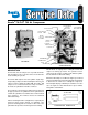
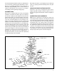
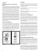
SD-01-335 ® Bendix® TU-FLO® 700 Air Compressor DISCHARGE CAP NUT DISCHARGE VALVE DISCHARGE VALVE SEAT DISCHARGE VALVE SPRING UNLOADER MECHANISM INLET VALVE SPRING INLET VALVE PISTON RINGS PISTON CRANKSHAFT EXTERIOR CONNECTING ROD CRANKCASE DESCRIPTION The function of the air compressor is to provide and maintain air under pressure to operate devices in the air brake and/or auxiliary air systems The Tu-Flo® 700 compressor is a two cylinder, single stage, reciprocating compressor with a rated displac
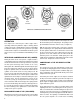
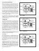
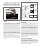
MACK "FOXHEAD" CUMMINS VARIOUS COMPRESSOR MOUNTINGS MACK OPERATION The compressor is driven by the vehicle engine and is operating continuously while the engine is running. Actual compression of air is controlled by the compressor unloading mechanism and the governor. The governor is generally mounted on the compressor and maintains the brake system air pressure to a preset maximum and minimum pressure level.
The Air Brake Charging System supplies the Discharge Line Optional “Ping” Tank Air Dryer compressed air for the braking system as well as other air accessories for the vehicle. The system usually consists of an air compressor, governor, discharge line, air dryer, and service reservoir.
DISCHARGE LINE TEMPERATURE When the temperature of the compressed air that enters the air dryer is within the normal range, the air dryer can remove most of the charging system oil. If the temperature of the compressed air is above the normal range, oil as oilvapor is able to pass through the air dryer and into the air system. Larger diameter discharge lines and/or longer discharge line lengths can help reduce the temperature.
COOLING Air flowing through the engine compartment from the action of the engine’s fan and the movement of the vehicle assists in cooling the crankcase. Coolant flowing from the engine’s cooling system through connecting lines enters the compressor and flows through the internal passages in the cylinder block and head and back to the engine. Proper cooling is important in maintaining discharge air temperatures below the 400°F recommended maximum.
Every 6 months, 1800 operating hours or after each 50,000 miles: Remove the discharge head fittings and inspect the compressor discharge port and discharge line for excessive carbon deposits. If excessive buildup is noted in either, the discharge line must be cleaned or replaced and the compressor checked more thoroughly, paying special attention to the air induction system, oil supply and return system, and proper cooling. If necessary, repair or replace the compressor.
Discard the inlet valves (3) and springs (2), the discharge valves (7), springs (8) and the discharge valve seats (6) if defective. A convenient method to indicate the above relationship is to use a metal scribe to mark the parts with numbers or lines. Do not use a marking method that can be wiped off or obliterated during rebuilding, such as chalk. Remove all compressor attachments such as governors, air strainers or inlet fittings, discharge fittings and pipe plugs.
If the pistons are removed from the rod, inspect the bronze wrist pin bushing. Press out and replace the bushing if it is excessively worn. (See inspection of parts) Discard the piston rings (18-20) and the connecting rod journal bearings (17). Discard the wrist pin bushings (21) if they were removed. CYLINDER BLOCK If the compressor is fitted with an air strainer, inlet elbow or governor remove the same.
be rebored or honed oversize. Oversized pistons and piston rings are available in .010 in., .020 in. and .030 in. oversizes. Cylinder bores must be smooth, straight, and round. Clearance between the cast iron pistons and cylinder bores should be between .002 in. minimum and .004 in. maximum. PISTON RINGS OIL RING .002 .
ASSEMBLY REPAIRS DISCHARGE VALVES, VALVE STOPS AND SEATS If the discharge valve seats merely show signs of slight wear, they can be dressed by using a lapping stone, grinding compound and grinding tool. Install the new discharge valve springs and valves. Screw in the discharge valve seats. Discharge valve travel should be between .030 in. to .046 in. General Note: All torques specified in this manual are assembly torques and can be expected to fall off after assembly is accomplished.
piston and secure same by inserting the new lockwire through the hole in piston and wrist pin and lock the wire by snapping the short 90 section into the lockwire hole in the bottom of the piston. Compressors built after November, 1976, will have the wrist pin secured by Teflon buttons in either end of the wrist pin, allowing the wrist pin to float. The Teflon buttons pc. no. 292392 may be used with either new or old wrist pins. The later design pistons have two rings above the wrist pin and one below.
COMPRESSOR TROUBLESHOOTING IMPORTANT: The troubleshooting contained in this section considers the compressor as an integrated component of the overall air brake charging system and assumes that an air dryer is in use. The troubleshooting presented will cover not only the compressor itself, but also other charging system devices as they relate to the compressor.
This troubleshooting guide obsoletes and supersedes all previous published troubleshooting information relative to Bendix air compressors. Advanced Troubleshooting Guide for Air Brake Compressors * The guide consists of an introduction to air brake charging system components, a table showing recommended vehicle maintenance schedules, and a troubleshooting symptom and remedy section with tests to diagnose most charging system problems.
Introduction to the Air Brake Charging System Powered by the vehicle engine, the air compressor builds the air pressure for the air brake system. The air compressor is typically cooled by the engine coolant system and lubricated by the engine oil supply.
Table A: Maintenance Schedule and Usage Guidelines Regularly scheduled maintenance is the single most important factor in maintaining the air brake charging system. Vehicle Used for: No. of Axles Column 1 Column 2 Typical Compressors Spec'd Discharge Line I.D. Length 1/2 in. 6 ft. Column 3 Recommended Air Dryer Cartridge Replacement1 Column 4 Recommended Reservoir Drain Schedule2 Column 5 Acceptable Reservoir Oil Contents3 at Regular Drain Interval e.g.
Air Brake Charging System Troubleshooting How to use this guide: Find the symptom(s) that you see, then move to the right to find the possible causes (“What it may indicate”) and remedies (“What you should do”). Review the warranty policy before performing any intrusive compressor maintenance. Unloader or cylinder head gasket replacement and resealing of the bottom cover plate are usually permitted under warranty. Follow all standard safety procedures when performing any maintenance.
Symptom: What it may indicate: What you should do: 2.0 Oil on the Outside of the Compressor Engine and/or other accessories leaking onto compressor. Find the source and repair. Return the vehicle to service. 2.1 Oil leaking at compressor / engine connections: (a)Leak at the front or rear (fuel pump, etc.) mounting flange. ð Repair or replace as necessary. If the mounting bolt torques are low, replace the gasket. (b)Leak at air inlet fitting. ð Replace the fitting gasket.
Symptom: What it may indicate: 4.0 Oil in Supply or Service Reservoir (air dryer installed) What you should do: Maintenance (a) If air brake charging system maintenance has not been (If a maintained Bendix performed.
Symptom: What it may indicate: 4.0 Oil in Supply or Service Reservoir* (air dryer installed) (continued) What you should do: Temperature (e) Air compressor discharge and/or air dryer inlet temperature too high. ð Check temperature as outlined in Test 3 on page 26. If temperatures are normal go to 4.0(h). (f) Insufficient coolant flow. ð Inspect coolant line. Replace as necessary (I.D. is 1/2"). ð Inspect the coolant lines for kinks and restrictions and fittings for restrictions. Replace as necessary.
Symptom: 4.0 Oil in Supply or Service Reservoir* (air dryer installed) (continued) What it may indicate: What you should do: Other (cont.) (i) Poorly filtered inlet air (poor air quality to compressor). Inspect the engine air cleaner. ð Check for leaking, damaged or defective compressor air inlet components (e.g. induction line, fittings, gaskets, filter bodies, etc.). Repair inlet components as needed. Note: Dirt ingestion will damage compressor and is not covered under warranty.
Symptom: What it may indicate: What you should do: 6.0 Excessive oil consumption in engine. A problem with engine or other engine accessory. ð See engine service manual. 7.0 Oil present at air dryer cartridge during maintenance. Air brake charging system is functioning normally. The engine service manual has more information. Oil shown leaking from an air dryer cartridge. ð Air dryers remove water and oil from the air brake charging system. A small amount of oil is normal.
Symptom: 9.0 Air brake charging system seems slow to build pressure. (continued) What it may indicate: What you should do: (f) Restricted discharge line. ð If discharge line is restricted: ð By more than 1/16" carbon build up, replace the discharge line (see Table A, column 2, on page 15 for recommended size) and go to Test 3 on page 26. ð By other restrictions (e.g. kinks). Replace the discharge line. See Table A, column 2, on page 15 for recommended size. Retest for air build.
Symptom: 10.0 Air charging system doesn’t build air. What it may indicate: What you should do: (a) Governor malfunction*. ð Go to Test 4 on page 27. (b) Restricted discharge line. ð See 9.0(f). (c) Air dryer heater malfunction: exhaust port frozen open. ð Replace air dryer heater. (d) Compressor malfunction. ð Replace the compressor only after making certain the preceding conditions do not exist.
Symptom: 12.0 Air dryer safety valve releases air. What it may indicate: What you should do: (a) Restriction between air dryer and reservoir. ð Inspect delivery lines to reservoir for restrictions and repair as needed. (b) Air dryer safety valve malfunction. ð Verify relief pressure is at vehicle or component manufacturer specifications. Replace if defective. (c) Air dryer performed. ð See Maintenance Schedule and Usage Guidelines (Table A, column 3, on page 15).
Symptom: 16.0 Compressor leaks air What it may indicate: (a) Compressor leaks connections or ports. at ð Check for leaking, damaged or defective compressor fittings, gaskets, etc. Repair or replace as necessary. ð Go to Test 6 on page 27. (c) Damaged gasket. head ð An air leak at the head gasket may indicate a downstream restriction such as a freezeup or carbon blockage and/or could indicate a defective or missing safety valve. Find blockage (go to 9.0(f) for details.) and then replace the compressor.
Tests Test 1: Excessive Oil Leakage at the Head Gasket Exterior leaks at the head gasket are not a sign that oil is being passed into the air charging system. Oil weepage at the head gasket does not prevent the compressor from building air. Observe the amount of weepage from the head gasket. If the oil is only around the cylinder head area, it is acceptable (return the vehicle to service), but, if the oil weepage extends down to the nameplate area of the compressor, the gasket can be replaced.
Tests (continued) Test 4: Governor Malfunction 1. Inspect control lines to and from the governor for restrictions (e.g. collapsed or kinked). Repair as necessary. 2. Using a calibrated external gauge in the supply reservoir, service reservoir, or reservoir port of the D-2™ governor, verify cut-in and cutout pressures are within vehicle OEM specification. 3. If the governor is malfunctioning, replace it. Test 5: Governor Control Line 1.
Appendix A: Information about the BASIC Test Kit (Bendix P/N 5013711) Service writer records info - including the number of days since all air tanks were drained - and fills out symptom checklist. Technician inspects items. days Bendix® Air System Inspection Cup (BASIC) Test Information START BASIC TEST Park vehicle on LEVEL ground. Chock wheels, drain air from system. Drain contents of ALL air tanks into BASIC cup Is there less than one unit of liquid? Vehicle OK. Return vehicle to service.
Appendix A continued: Information about the BASIC Test Kit (Bendix P/N 5013711) ® Filling in the Checklist for the Bendix Air System Inspection Cup (BASIC) Test Note: Follow all standard safety precautions. For vehicles using a desiccant air dryer.
Appendix A continued: Information about the BASIC Test Kit (Bendix P/N 5013711) ® Filling in the Checklist for the Bendix Air System Inspection Cup (BASIC) Test Note: Follow all standard safety precautions. For vehicles using a desiccant air dryer. 2. Record amount of oil found: The Technician uses the chart (label) on the BASIC test cup to help decide the action to take, based on the amount of oil found.
Appendix B Technical Bulletin Bulletin No.: TCH-008-021 Subject: Effective Date: 11/1/92 Page: 1 of 2 Air Brake System - Cold Weather Operation Tips As the cold weather approaches, operators and fleets alike begin to look to their vehicles with an eye toward “winterization”, and particularly what can be done to guard against air system freeze-up. Here are some basic “Tips” for operation in the cold weather.
Appendix B: Continued Bulletin No.: TCH-008-021 Effective Date: 11/1/92 Page: 2 of 2 High Duty Cycle Vehicles (City Transit Coaches, Refuse Haulers, Etc.) The maximum discharge line length is 16 feet. Length I.D. min. Other Requirements 10-16 ft. ½ in. None If the discharge line length must be less than 10 feet or greater than 16 feet, contact your local Bendix representative.
Appendix B: Continued Technical Bulletin Bulletin No.: TCH-008-022 Subject: Additional Effective Date: 1/1/1994 Page: 1 of 1 Cold Weather Operation Tips for the Air Brake System Last year we published Bulletin PRO-08-21 which provided some guidelines for “winterizing” a vehicle air brake system. Here are some additional suggestions for making cold weather vehicle operation just a little more bearable.
BW1422 © 2004 Bendix Commercial Vehicle Systems LLC All rights reserved. 10/2004 Printed in U.S.A.