
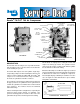
User's Manual


7
A convenient method to indicate the above relationship is to
use a metal scribe to mark the parts with numbers or lines.
Do not use a marking method that can be wiped off or
obliterated during rebuilding, such as chalk. Remove all
compressor attachments such as governors, air strainers
or inlet fittings, discharge fittings and pipe plugs.
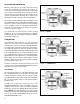
CYLINDER HEAD
Remove the six cylinder head cap screws (1) and tap the
head with a soft mallet to break the gasket seal. Remove
the inlet valve springs (2) and spring inserts (35) from the
head and inlet valves (3) from their guides in the block.
Remove inlet valve guides (4) from around the inlet valve
seats (34) on the block taking care not to damage seats.
Scrape off any gasket material (5) from the cylinder head
and block. Unscrew the discharge valve seats (6) from the
head and remove the discharge valves (7) and springs (8).
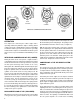
Inspect the discharge valve seats (2) for nicks, cracks, and
excessive wear and replace if necessary. The discharge valve
cap/nut stops (9) should be inspected for wear and replaced
if excessive peening has occurred. To determine if excessive
peening has occurred, measure the discharge valve travel.
Discharge valve travel must not exceed .046 inches. If
discharge valve travel is excessive, replace the cap nut/stop
assembly, discharge valve and spring.
Discard the inlet valves (3) and springs (2), the discharge
valves (7), springs (8) and the discharge valve seats (6) if
defective.
CRANKCASE BASE PLATE OR ADAPTER
Remove the cap screws securing the base plate or base
adapter. Tap with soft mallet to break the gasket seal (11).
Scrape off any gasket material from crankcase and plate or
adapter.
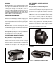
CONNECTING ROD ASSEMBLIES
(Note: Before removing the connecting rods, mark each
connecting rod and its cap. Each connecting rod is matched
to its own cap for proper bearing fit, and these parts must
not be interchanged.) Remove the connecting rod bolts (13)
and bearing caps (14). Push the piston (15) with the
connecting rods (16) attached out the top of the cylinders of
the cylinder block. Replace the bearing caps (14) on their
respective connecting rods. Remove the piston rings from
the pistons. If the pistons are to be removed from the
connecting rods, remove the teflon plugs (36) and press the
wrist pins (37) from the pistons and connecting rods.
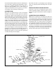
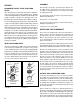
FIGURE 8 - TU-FLO
®
700 AIR COMPRESSOR (THRU DRIVE) EXPLODED VIEW
34
35
36
28
REAR COVER
20
18
20
19
18
19
6
7
8
9
1
5
2
3
4
CYLINDER BLOCK
16
17
CRANKSHAFT
14
13
26
FLANGE
ADAPTER
21
24
25
29
30
REAR COVER
GASKET
31
32
11
27 22
26
10
12
CYLINDER HEAD
37
33
23
34
35
15
36
37
CRANKCASE