
User's Manual


1
Bendix
®
SL-3
™
& SL-4
™
Stop Light Switch
SD-06-1800
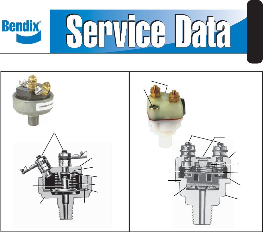
FIGURE 1 - BENDIX
®
SL-3
™
STOP LIGHT SWITCH
FIGURE 2 - BENDIX
®
SL-4
™
STOP LIGHT SWITCH
DESCRIPTION
The stop light switch is an electro-pneumatic switch and
operates in conjunction with the brake valve and stop
lights by completing the electrical circuit when a brake
application is made.
OPERATION
When a brake application is made, air pressure from
the brake valve enters the cavity below the diaphragm.
At approximately 5 psi, the air pressure underneath
the diaphragm overcomes the force of the spring and
moves the piston or plunger until the contact points close,
completing the stop light electrical circuit and lighting the
stop lights.
PREVENTIVE MAINTENANCE
Important: Review the Bendix Warranty Policy before
performing any intrusive maintenance procedures. A
warranty may be voided if intrusive maintenance is
performed during the warranty period.
No two vehicles operate under identical conditions; as
a result, maintenance intervals may vary. Experience is
a valuable guide in determining the best maintenance
interval for air brake system components. At a minimum,
the Bendix
®
SL-3
™
and SL-4
™
switches should be inspected
every 6 months or 1500 operating hours, whichever comes
first, for proper operation and electrical connections.
Should the SL-3
™
or SL-4
™
switch not meet the elements
of the operational tests noted in this document, further
investigation and service of the valve may be required.
8
COVER
11
SPRING
CONTACT
13
PISTON
BODY
14
O-RING
DIAPHRAGM
12
CONTACT
STRIP
9
TERMINAL
SCREWS
10
VENT
PLUG
15
GASKET
7
MACHINE
SCREWS
1
COVER
6
DIAPHRAGM
BODY
3
SPRING
CONTACTS
2
TERMINAL
SCREWS
4
PLUNGER
7
TERMINAL
CONNECTOR
5
WASHER