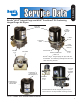
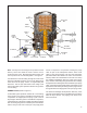
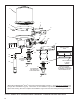
SD-08-2414 ® Bendix® AD-IP® Integral Purge and AD-IP® PuraGuard® Oil Coalescing Integral Purge Air Dryers DESICCANT CARTRIDGE CABLE MOUNTING BRACKET CONTROL PORT MOUNTING CABLE LOWER MOUNTING BRACKET DELIVERY PORT SAFETY VALVE DISCHARGE HEATER & THERMOSTAT CONNECTOR SUPPLY PORT Bendix® AD-IP® integral purge air dryer with the PuraGuard® oil coalescing cartridge and the new cable mounting bracket.
GENERAL SAFETY GUIDELINES WARNING! PLEASE READ AND FOLLOW THESE INSTRUCTIONS TO AVOID PERSONAL INJURY OR DEATH: When working on or around a vehicle, the following guidelines should be observed AT ALL TIMES: ▲ Park the vehicle on a level surface, apply the parking brakes and always block the wheels. Always wear personal protection equipment. ▲ Stop the engine and remove the ignition key when working under or around the vehicle.
DESCRIPTION IMPORTANT The function of the Bendix® AD-IP® integral purge air dryer — and the Bendix® AD-IP® integral purge air dryer with PuraGuard® oil coalescing — is to collect and remove air system contaminants in solid, liquid and aerosol form, before they enter the brake system. They provide clean, dry air to the components of the brake system which increases the life of the system and reduces maintenance costs. Daily manual draining of the reservoirs is eliminated.
Note 1: The Bendix® AD-IP® air dryer and reservoir system purge piston has a purge control channel drain. This allows any condensation in this area to flow past a diaphragm in the top of the purge piston and out through a channel in the middle of the central bolt of the purge assembly to be drained. During the purge cycle this drain is closed.
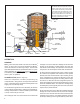
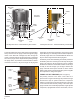
OIL SEPARATOR DESICCANT BED PURGE ORIFICE PURGE CONTROL LINE PURGE VOLUME CONTROL PORT SUPPLY PORT DELIVERY CHECK VALVE GOVERNOR DISCHARGE PORT COMPRESSOR ENGINE TURBO TURBO CUT-OFF VALVE EXHAUST PURGE VALVE FIGURE 3 - BENDIX® AD-IP® INTEGRAL PURGE AIR DRYER PURGE CYCLE Note: the early end cover designs incorporated a vertical delivery check valve while the newer versions have a horizontal check valve. Both have the same function, but the components are not interchangeable. See Figure 4.
DESICCANT BED SPRING OIL SEPARATOR DESICCANT CARTRIDGE PURGE ORIFICE PIPE PLUG PURGE VOLUME CONTROL PORT CHECK VALVE (BLACK) SUPPLY PORT DELIVERY PORT TURBO CUT-OFF VALVE PURGE VALVE CARTRIDGE BOLT DELIVERY PORT Old Style End Cover -Vertical Delivery Check Valve CARTRIDGE BOLT O-RING CHECK VALVE (WHITE) New Style End Cover - Horizontal Delivery Check Valve FIGURE 4 - BENDIX® AD-IP® AIR DRYER SECTIONAL VIEW The actual reactivation of the desiccant drying bed begins as dry air flows from the p
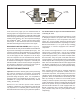
3 O-RING GROOVES 2 O-RING GROOVES PURGE VALVE HOUSING STANDARD PURGE VALVE DLU PURGE VALVE FIGURE 6 - BENDIX® AD-IP® AND AD-IP DLU AIR DRYER PURGE VALVES At the onset of the purge cycle, the downward travel of the purge piston is stopped when the turbo cut-off valve (tapered portion of purge piston) contacts its mating metal seat in the purge valve housing.
Notes: 1. Visually check for physical damage to the air dryer such as chaffed or broken air and electrical lines and broken or missing parts. 2. Check mounting bolts for tightness. Re-torque to 270–385 in-lbs. 3. Perform the Operation & Leakage Tests listed in this publication. This air dryer is intended to remove moisture and other contaminants normally found in the air brake system. Do not inject alcohol, anti-freeze, or other de-icing substances into or upstream of the air dryer.
Maintenance Kits Description Piece Number Cartridge Bolt Kit 109498 Desiccant Cartridge Service New 065624 Desiccant Cartridge Remanufactured 109493X Bendix® PuraGuard® Coalescing Cartridge Kit Service New 065624PG PuraGuard Coalescing Cartridge Kit Reman Exchange 109493PGX Delivery Check Valve Kit 109494 Exhaust Cover Kit HEATER & THERMOSTAT CONNECTOR AD-IP® AIR DRYER END COVER 5011327 Extended Purge Kit 3/8" U-Bolt; 90in3 Reservoir 5012561N Extended Purge Kit 3/8" U-Bolt; 288in3 Reserv
11 1 4 5 3 19 6 22 21 20 9 23 24 25 SLIDE INSTALLATION RING INTO PURGE BORE 16 2 17 18 8 12 13 10 15 STANDARD STYLE PURGE VALVE 7 *16 18 14 15 APPLY LUBRICANT TO INSIDE SURFACE INSTALLATION RING (NOTE THE ORIENTATION OF THE BEVEL OF THE RING BEFORE INSTALLATION.) DISCHARGE LINE UNLOADED (DLU) STYLE PURGE VALVE 14 *Most OE installed Bendix® AD-IP® air dryers manufactured after January 1, 2014 will not be equipped with a purge valve installation ring (16).
Item Description Qty.
INSTALL CABLE ASSEMBLY IN THIS AREA 32 33 DELIVERY PORT LOWER BRACKET MOUNTING HOLES 35 34 31 8 INSERT CABLE ASSEMBLY IN UPPER BRACKET WING HOLE AS SHOWN 9 7 FIGURE 10 - BENDIX® AD-IP® AIR DRYER CABLE BRACKET INSTALLATION There are two types of upper mounting brackets; saddle type (shown in Figure 8), and cable type (shown in Figure 10). Refer to the appropriate figure for the type of air dryer being serviced. 6.
ASSEMBLY Disassembly of the desiccant cartridge assembly should not be attempted! Detail parts for the cartridge are not available and the cartridge contains a 150# spring which can not be mechanically caged. For purge valve assembly instructions refer to the instruction sheet included in the kit. A listing of maintenance kits is included in this document. 1. Complete the purge valve installation per the installation instructions provided in the service kit. 2.
VEHICLE APPLICATION REQUIREMENTS 8. Using an adjustable wrench or a socket, tighten the desiccant cartridge bolt (10), to secure the desiccant cartridge (11) to the end cover (6). Torque the desiccant cartridge bolt to 65–75 ft-lbs (40 ft-lbs minimum). Do not over torque. BENDIX® AD-IP® AIR DRYER INSTALLATION 1.
VEHICLE PREPARATION 1. Park the vehicle on a level surface and prevent movement by means other than the brakes. 2. Drain all reservoirs to 0 psi. LOCATING BENDIX® AD-IP® AIR DRYER ON THE VEHICLE 1. The Bendix ® AD-IP ® air dryer must be mounted vertically (purge exhaust toward road surface) outside the engine compartment in an area of air flow while the vehicle is in motion. The AD-IP air dryer must not be exposed to direct wheel splash.
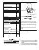
CONNECTING THE AIR LINES GOVERNOR PURGE CONTROL LINE TO CON PORT AD-IP® AIR DRYER COMPRESSOR DISCHARGE LINE SUPPLY RES. DELIVERY LINE FROM DEL PORT HEATER & ON AD-IP® AIR THERMOSTAT DRYER LEAD TO GROUND FIGURE 11 - BENDIX® AD-IP® AIR DRYER INSTALLATION FRAME RAIL STAR WASHER 1/4” or 3/8” EYELET NUT GROUND LEAD WEATHERPROOF POWER LEAD SPLICE 14 GAUGE POWER WIRE FROM VEHICLE WIRE HARNESS CONNECTOR (TO AIR DRYER) FIGURE 12 - WIRING - REMOTE POWER & LOCAL GROUND 16 1.
3. The wire harness—available in the Wire Harness and Splice Kit from authorized Bendix® parts outlets —is not included with the service replacement air dryer. When using this kit, if it becomes necessary to lengthen the harness, use only 14 gauge wire. When splicing wires, ensure all wire splices are waterproofed. 4. Tie wrap or support all electrical wires leading to the Bendix® AD-IP® air dryer at 6–8 inch intervals. Note: Wires should have sufficient slack and not be completely taught.
BENDIX® AD-IP® AIR DRYER TROUBLESHOOTING CHART SYMPTOMS CAUSE REMEDY 1. Air dryer is constantly “cycling” or purging. Air dryer purges frequently (every four (4) minutes or less while vehicle is idling). A. Excessive system leakage. IMPORTANT: Note whether air pressure loss is shown on dash gauge(s). Pressure loss SHOWN on gauges is caused by service brake system or component leakage. Pressure loss NOT SHOWN on gauges is caused by supply system or component leakage. A.
BENDIX® AD-IP® AIR DRYER TROUBLESHOOTING CHART SYMPTOMS CAUSE REMEDY 1. Air dryer is constantly “cycling” or purging. Air dryer purges frequently (every four (4) minutes or less while vehicle is idling) (continued). A. Excessive system leakage. IMPORTANT: Note whether air pressure loss is shown on dash gauge(s). Pressure loss SHOWN on the gauges is caused by service brake system or component leakage. Pressure loss NOT SHOWN on gauges is caused by supply system or component leakage. (continued) 1.
BENDIX® AD-IP® AIR DRYER TROUBLESHOOTING CHART SYMPTOMS CAUSE REMEDY 1. Air dryer is constantly “cycling” or purging. Air dryer purges frequently (every four (4) minutes, or less, while vehicle is idling) (continued). A. Excessive system leakage. IMPORTANT: Note whether air pressure loss is shown on dash gauge(s). Pressure loss SHOWN on gauges is caused by service brake system or component leakage. Pressure loss NOT SHOWN on gauges is caused by supply system or component leakage. (continued) 6.
BENDIX® AD-IP® AIR DRYER TROUBLESHOOTING CHART SYMPTOMS CAUSE REMEDY 2. Water and/or oil in the supply or service reservoir. A. Improper discharge line length or improper line material. The maximum air dryer inlet temperature is exceeded. A. Refer to Connecting the Air Lines section as well as Appendix A, Table A columns 1 & 2 then check line size and length. B. Air system charged from an outside air source (outside air not passing through air dryer). B.
BENDIX® AD-IP® AIR DRYER TROUBLESHOOTING CHART SYMPTOMS CAUSE 2. Water and/or oil in the supply or service reservoir (continued). E. (Continued) F. Air compressor discharge and/or air dryer inlet temperature too high. REMEDY Air Compressor Size - Although the Bendix ® AD-IP® air dryer can be used in conjunction with larger compressors, it was designed primarily for units rated for up to 30 CFM.
BENDIX® AD-IP® AIR DRYER TROUBLESHOOTING CHART SYMPTOMS CAUSE REMEDY 2. Water and/or oil in the supply or service reservoir (continued). G. Compressor malfunction. G. If you found excessive oil present in the service reservoir and you did not find any issues above, the compressor may be passing oil. Test the compressor using the Bendix® BASIC™ cup method as described in the Bendix compressor service manual and referred to in Appendix A, Table A, column 5. Replace compressor.
BENDIX® AD-IP® AIR DRYER TROUBLESHOOTING CHART SYMPTOMS CAUSE REMEDY 5. Constant exhaust of air at air dryer purge valve exhaust. (Charge mode.) A. Air dryer purge valve is leaking excessively. A. With the compressor loaded, apply a soap solution on the purge valve exhaust, to test for excessive leakage. Refer to Technical Bulletin TCH-008-040. Repair the purge valve as necessary. B.
BENDIX® AD-IP® AIR DRYER TROUBLESHOOTING CHART SYMPTOMS CAUSE REMEDY 8. Desiccant material being expelled from the air dryer purge valve exhaust (may look like whitish liquid or paste or small beads.) A. This symptom is almost always accompanied by one, or more, of Symptoms 1, 2, 3, 4 and 5. See related causes for these symptoms above. A. See Causes and Remedies for Symptoms 1, 2, 3, 4 and 5. B. Air dryer not securely mounted. (Excessive vibration.) B. Vibration should be held to minimum.
Appendix A Table A: Maintenance Schedule and Usage Guidelines Regularly scheduled maintenance is the single most important factor in maintaining the air brake charging system. Column 1 Column 2 Typical Discharge Compressors Line No. of Spec'd Axles I.D. Length Vehicle Used for: Low Air Use 1/2 in. 5 or less e.g. Line haul single trailer with air suspension, RV, school bus. 5 or less High Air Use e.g.
Appendix B Additional Troubleshooting Information The troubleshooting procedure presented on the following pages has been excerpted from a laminated card entitled: Troubleshooting Charging and Air Supply Systems (BW1779). The complete card can be ordered from the Bendix Marketing Center at www.bendix.com. It is presented here because of the air dryers connection to the supply air system and for convenience. The procedure is not all inclusive but rather represents the most commonly encountered complaints.
COMPLAINTS COMMON TO THE CHARGING & AIR SUPPLY SYSTEM Complaint: Can Not Build System Pressure • Discharge line plugged or restricted: see Common Test 1. • Air pressure trapped between the governor and compressor unloaders: see Common Test 2. • Blow leakage at air dryer exhaust: see Common Test 3. Complaint: Air System Builds Too Slow • Discharge line restricted: see Common Test 1. • Discharge line leakage: see Common Test 5. • Air leaking at the air dryer exhaust: see Common Test 3.
COMPLAINTS COMMON TO THE CHARGING & AIR SUPPLY SYSTEM Complaint: System Pressure Goes to 150+ psi • Drain the air system to zero (0) psi, remove/disconnect the governor from the compressor. Start the engine and note the air pressure rise on the dash gauges. Apply 120 psi of shop air to compressor unloader port. If the air pressure continues to rise, repair compressor unloaders or replace compressor. If air ceases to rise, repair or replace governor.
TESTS COMMON TO MORE THAN ONE COMPLAINT 1. Discharge plugged or restricted • Connect a temporary discharge line from the compressor discharge port to the supply reservoir and re-check the build-up. If the system build-up is OK then replace the plugged discharge line. If the build-up is NOT OK, go to next cause. 2. Air pressure trapped between the governor and the compressor • Verify the safety valve operation, then remove or disconnect the governor from the compressor and check build-up.