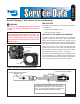
SD-13-3333 Bendix® Wingman® ACB (Active Cruise with Braking) DESCRIPTION WARNING Improper use of the Wingman ACB system can result in a collision causing property damage, serious injuries, or death. The driver is always responsible for the control and safe operation of the vehicle at all times. The Bendix Wingman ACB system does not replace the need for a skilled, alert professional driver, reacting appropriately and in a timely manner, and using safe driving practices.
Once cruise control is set and the system is maintaining a set following distance between you and the vehicle in front, if the vehicle in front of you slows down below the cruise control’s set speed, the Bendix® Wingman® ACB system will intervene and, as necessary, in this order: (a) reduce the engine throttle, then (b) apply the engine retarder, then (c) apply the foundation brakes, Because the Wingman ACB system operates along with normal cruise control, all the typical features built into cruise co
1.0 OPERATION SECTION Section Index 1.01 Important Safety Information/ When Not to Use Bendix Wingman ACB Active cruise with Braking . . . . . . . . . . . 3 1.02 System Components. . . . . . . . . . . . . . 4 1.04 What to Expect When Using Wingman ACB . . . . . . . . . . . . . . . . 5-6 1.05 How a Driver Interacts with Wingman ACB . . . . . . . . . . . . . . . . . 7 1.06 Following Distance . . . . . . . . . . . . . . . 8 1.
AUTOMATIC FOUNDATION BRAKE APPLICATIONS Also see the Indications and Alerts section of this manual on page 16 for more detailed information about the alerts. The vehicle automatically manages foundation brake priorities among the various vehicle systems that use the foundation brakes, such as Bendix® Wingman® ACB system, Bendix® ESP® Electronic Stability Program, Bendix® ATC (Automatic Traction Control) and Bendix® ABS (Antilock Braking System).
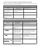
1.04 WHAT TO EXPECT WHEN USING THE BENDIX® WINGMAN® ACB SYSTEM Table 1, parts 1-3, illustrate what to expect from the Wingman ACB system in various driving situations. Typical system indications and actions to expect from the system are illustrated. What to Expect (1.04) Part One: All driving scenarios (Cruise is either “on” or “off”) Typical System Indication/Alerts Situation A broken-down vehicle is stationary in the lane in which the truck is traveling.
What to Expect (1.04) Part Two: Cruise control “on” and speed “set” Typical System Indication/Alerts Situation Going down a grade with a detected forward vehicle. DO NOT USE cruise control on downhill grades. Typical System Actions DO NOT USE cruise control on downhill grades. Cruise control should NOT be used on downhill grades - see page 3. (See the CDL manual instructions on proper gear usage for down grades.
1.05 HOW A DRIVER INTERACTS WITH BENDIX® WINGMAN® ACB Table 2 illustrates how the Wingman ACB system will respond to various actions a driver may take when using Wingman ACB system on the road. The driver is always responsible for the control and safe operation of the vehicle at all times. The Bendix Wingman ACB system does not replace the need for a skilled, alert professional driver, reacting appropriately and in a timely manner, and using safe driving practices.
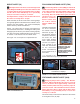
THE FORWARD VEHICLE DETECTED ICON When cruise control is switched on and set and a vehicle ahead of you is detected by the radar, the detected forward vehicle icon, or similar will illuminate on the vehicle dashboard. This is an indication to the driver that the Wingman ACB system is actively managing the distance between your vehicle and the vehicle ahead, and may intervene automatically, if needed. See Figure 6 for examples. 1.
IMPACT ALERT (IA) FOLLOWING DISTANCE ALERT (FDA) The Impact Alert is the most severe warning issued by the Wingman ACB system. This alert indicates that a collision with the detected forward vehicle is likely and the driver must immediately act to potentially avoid, or lessen the severity of, a collision.
The driver should be especially careful when approaching certain types of vehicles or objects. The Wingman ACB radar may not be able to detect vehicles and objects with limited metal surfaces (such as recreational vehicles, horse-drawn buggies, motorcycles, logging trailers, etc.). NOTE: Entering a curve may reduce the alert time to less than three (3) seconds. system foundation brake applications for at least 20 minutes.
2.0 MAINTENANCE SECTION Section Index 2.1 General Safety Guidelines . . . . . . . . . . . 11 2.2 Equipment Maintenance: Brake System and ABS Functionality . . . . . . . . . . . . . 12 2.3 2.4 System Preventive Maintenance. . . . . . . . 12 Additional Support at www.bendix.com . . . . 12 2.
2.2 EQUIPMENT MAINTENANCE: BRAKE SYSTEM AND ABS FUNCTIONALITY Importance of Antilock Braking System (ABS) Maintenance – Optimal Bendix® Wingman® ACB system braking requires a properly maintained ABS system, without any active ABS Diagnostic Trouble Codes (DTCs). Have active DTCs repaired by a qualified technician. Any ABS DTCs will cause Wingman ACB to deactivate.
This section introduces three initial steps to accurately troubleshoot the Bendix® Wingman® ACB system. 3.0 INTRODUCTION TO TROUBLESHOOTING SECTION Section Index 3.1 Troubleshooting Basics . . . . . . . . . . . . 13 3.2 Narrowing Down the Problem . . . . . . . 14-15 3.3 Overview of Possible Issues . . . . . . . . . . 16 We recommend reading this introductory section, as well as the Troubleshooting/Diagnostics Section (4.0), before performing any troubleshooting.
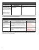
3.2 NARROWING DOWN THE PROBLEM Use the questions found in Table 3.2 below to help assess if the Bendix® Wingman® ACB system is not performing correctly. Be sure to have a thorough understanding of the system’s normal behavior; this will reduce the troubleshooting time. The table provides a guide to basic troubleshooting questions and possible corrective actions. Items in Italics cross-reference to the service procedures in this manual to repair the condition described.
Narrowing Down the Problem (3.2) Questions Does the mounting bracket look damaged or tampered with? Next Steps Other than expected surface scratches or some discoloration over time, there should be no visible damage to the radar sensor bracket assembly. If so, realign the radar sensor vertically and laterally. If radar sensor alignment can not be held in place, the bracket assembly must be replaced. Verify the bumper is not damaged. • • Check the Vertical Alignment (6.07) and adjust if needed.
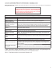
3.3 OVERVIEW OF POSSIBLE ISSUES Some customer issues are actually misunderstandings of how the Bendix® Wingman® ACB system performs normally. Use Table 5 below to learn the causes of potential issues if Wingman ACB is not performing correctly. Some issues can be investigated by a visual inspection. Others may cause a diagnostic trouble code (DTC) to be logged: See Section 4.3: Diagnostic Trouble Codes. Overview of Possible Issues (3.3) Issue System familiarity Description Verify the system functionality.
4.0 TROUBLESHOOTING/ DIAGNOSTICS SECTION 4.1 BENDIX® ACOM® DIAGNOSTICS SOFTWARE Section Index ACom Diagnostics is a PC-based software program available as a free download from the Bendix web site (www. bendix.com) or on a CD from the Bendix Literature Center. This software provides the technician with access to all the available ECU diagnostic information and configuration capability. For Bendix Wingman ACB diagnostics, use ACom Diagnostics version 6.3 (or higher). 4.
The Bendix® ACom® Diagnostics for ABS User Guide is available for download at the www.bendix.com web site and should be used as a reference to all functions of the ACom service tool. In general, the protocol for Wingman ACB is described as CAN or CAN 250. (See Figure 15 for an example of an adapter compatible with Wingman ACB). The Bendix® EC-60™ controller protocol will be described as J1708. 4.
4.3 TABLE OF BENDIX® WINGMAN® ACB DIAGNOSTIC TROUBLE CODES (DTCs) See Table 6 below: Table of Diagnostic Trouble Codes (DTCs), Causes and Recommended Actions (4.3) DTC Actions 40 - Short to ground 41 - Short to battery Voltage too high (includes DTCs 89, 92) Voltage too low (includes DTCs 90, 91) Possible causes: These trouble codes result from incorrect ignition, battery supply voltage, or wiring harness issues as measured at the radar sensor. Review the following sections: • 4.
Table of Diagnostic Trouble Codes (DTCs), Causes and Recommended Actions (4.
Table of Diagnostic Trouble Codes (DTCs), Causes and Recommended Actions (4.3) DTC 162 - DTC showing a problem in the interface of the Wingman ACB brake system. Find and correct all other Diagnostic Trouble Codes (DTCs) using Acom before attempting to diagnose this trouble code. From the starter screen select EC-60 and “Start with ECU”. When prompted to choose the hardware interface, confirm that the Bendix® EC-60™ controller protocol used will be J1708.
Table of Diagnostic Trouble Codes (DTCs), Causes and Recommended Actions (4.3) DTC Actions 186 – J1939 Outside air temperature signal not available or signal in error. (This trouble code alone will not cause Wingman ACB to disable. The heater on the lens of the radar sensor will not operate and will not prevent ice or snow build up. The radar sensor may become blocked and then Wingman ACB will disable, logging a trouble code 201.) Review the following sections: • 4.
Table of Diagnostic Trouble Codes (DTCs), Causes and Recommended Actions (4.3) DTC 203 - Wingman ACB and ABS have a mismatch of the Collision Mitigation Configuration Actions Possible causes: • The controller is recognizing that there are components installed that have part numbers incompatible with the current system configuration.
4.6 SERIAL DATA (J1939) COMMUNICATIONS LINK Check for a loss of communications between the Bendix® Wingman® ACB system radar sensor, the ABS controller, the engine ECU, and other devices connected to the J1939 link. Check for damaged or reversed J1939 wiring. Check for corroded or damaged connectors and loose connections. Using procedures described by the vehicle manufacturer, verify the presence of the engine ECU and the ABS controller on the J1939 link. Verify the engine ECU con figuration.
5.0 OTHER SYSTEM FEATURES SECTION Section Index 5.1 Reading Bendix® Wingman® ACB 5.2 System Key Indicators Diagnostic . . . . . . . . . . . . 25 Trouble Code (DTC) Self Clearing . . . . . . . 25 5.3 Following Distance Adjustment Switch (Optional) . . . . . . . . . . . . . . . . . . . 25 5.4 Configuring Wingman ACB Following Distance Alerts . . . . . . . . . . . . . . . . . 26 5.5 Extracting Bendix® Wingman® ACB System Data. . . . . . . . . . . . . . . . . . 27 5.5.1 Data Availability . . . . . .
5.4 CONFIGURING BENDIX® WINGMAN® ACB FOLLOWING DISTANCE ALERTS Multiple alert and distance setting strategies, known as Following Distance Alert (FDA) configurations, can be chosen using the Bendix® ACom® Diagnostics tool. In ACom software (version 6.3 or higher), the service technician will find a selection box called “Configuration Number” which gives the service technician the choices shown in Figure 18 and in Table 8.
5.5.3 EXTRACTING DATA AND SAVING A REPORT The ACom Diagnostics tool and User Guide is available online at “ABS Software” link under “Services and Support” on the Bendix website (www.bendix.com). Use the User Guide for specific instructions on extracting data from the Wingman ACB system. After a successful connection, the service technician will be presented with the window shown in Figure 20. Select “Start ACB Data Log”. The service technician will be asked to enter the vehicle ID and mileage.
FIGURE 22 - TYPICAL WINGMAN ACB VEHICLE REPORT
6.0 BENDIX® WINGMAN® ADVANCED™ RADAR SENSOR MOUNTING AND INSTALLATION SECTION Note: This section only covers Bendix-supplied mounting arrangements. (See Figure 23 for Bendix-supplied mounting arrangement. At time of printing, Bendixsupported mounting arrangements are used on Mack® and Volvo® trucks). For other mounting arrangements consult the OEM. Section Index 6.01 Vehicle Applications . . . . . . . . . . . . . . . 29 6.02 Radar Sensor Mounting . . . . . . . . . . . . . 29 6.03 Replacement Parts . . . . .
6.04 RADAR SENSOR ALIGNMENT Accurate vertical and lateral alignment of the radar sensor is critical for proper operation of Bendix ® Wingman ® Advanced™. Improper alignment will cause false warnings, missed warnings and a diagnostic trouble code in the system. The radar sensor is mounted to the front of the vehicle using an adjustable bracket. Use the following procedures to align the radar sensor in its adjustable bracket: 6.07.
Follow the manufacturer’s instructions (typically digital inclinometers have a “SET” button for this purpose). Vertical Alignment Bubble Level Check the alignment with the alignment tool in position so that it straddles the radar sensor. Verify that the radar is aligned downward, towards the road surface in front of the vehicle, by -1.3° (± 0.8°), when measured by an inclinometer set to zero on the vehicle’s frame. If the sensor is not aligned correctly, follow the instructions in section 6.08.
1. Be sure the vehicle is prepared as shown in Sections 6.07.1-3. 2. With the Bendix alignment tool still in place, loosen the four vertical position screws. DO NOT remove these screws. See Figure 31. During the adjustment, turn the vertical alignment screw clockwise or counterclockwise depending on the vertical direction (up or down) needed. Clockwise aligns the radar sensor up and counterclockwise moves the radar sensor down. 3.
Laser Light Line Lateral Adjustment Screw FIGURE 37 - LATERAL ADJUSTMENT 2. See Figure 37. Adjust the lateral adjustment screw until the desired alignment is reached. DO NOT remove the screws. Use steps 4 through 7 in Section 6.09: Check Lateral Alignment section to measure. FIGURE 35 - LATERAL ALIGNMENT VERIFICATION NOTE: The lateral alignment also can be checked with Bendix ACom® Diagnostics (version 6.3 or higher). A value between -0.8° and 0.8° is acceptable and the system should operate normally.
APPENDIX A - TROUBLESHOOTING CHECKLIST Appendix A Troubleshooting Checklist Detailed Scenarios and Tests Record Driver’s Answers for Follow-up with Bendix Does the vehicle maintain its set speed when cruise control is switched on and set? Yes No _____________ Is the cruise control “set” icon displayed? Yes No _____________ Yes No _____________ While following a forward vehicle within radar range and the cruise control switched on and set, observe the following: Is the forward vehicle detected i
Appendix A Troubleshooting Checklist Detailed Scenarios and Tests Record Driver’s Answers for Follow-up with Bendix With cruise engaged, and a faster vehicle passes your vehicle on the left or right on a straight or slightly curvy road: Does your vehicle throttle up and try to keep pace with the faster moving vehicle? Yes No _____________ Does it give a following distance alert? Yes No _____________ Does your vehicle slow and Advanced maintain the following distance? Yes No _____________ Is th
APPENDIX B - DRIVER INTERFACE UNIT (DIU): DISPLAYS AND ALERTS Appendix B Driver Interface Unit: Displays & Alerts B1 Operator Interface The Bendix® Wingman® ACB system is either integrated into the vehicle's dash or console, or uses the Bendix® Driver Interface Unit (DIU) to communicate with the driver. (For integrated systems, see the vehicle operator’s manual for more information.) This Section describes the functions of the DIU.
Appendix B Driver Interface Unit: Displays & Alerts When the initialization sequence is complete, the following screen is displayed for approximately 3 seconds to indicate the features available to the driver. (No LEDs Illuminated) ACB Bendix Next, the DIU will enter normal operation. Under normal operation, the screen is: (No LEDs Illuminated) If the Bendix® Wingman® ACB goes into self-test mode, the DIU may briefly display the “Bendix Self-Test” screen.
Appendix B Driver Interface Unit: Displays & Alerts B1.3 Volume Selecting “Volume” from the main menu displays the following screen: (No LEDs Illuminated) The driver uses the up ( this menu item. )/down ( Volume ) arrow buttons to change the volume. Pressing the “OK” button exits The modified volume setting will be retained through ignition cycles unless configured not to do so. If not configured, the volume setting will default to 100% on each new ignition cycle.
Appendix B Driver Interface Unit: Displays & Alerts B1.6 US/Metric From this menu item, the user may select whether English or Metric units are displayed. For instance in “metric” mode, the following distance is shown in meters. In “US” mode, the following distance is shown in feet. B1.
Appendix B Driver Interface Unit: Displays & Alerts B2.0 Driver Demonstration Mode Selecting Demo from the main menu starts a demonstration mode that shows the various lights, display screens, and sounds produced by the DIU – along with a brief explanation of their meaning – for the configured features. Pressing the down ( ) arrow button advances through the screens. The up ( ) arrow button has no functionality in this mode. The mode may be exited at any time by pressing the OK button.
Appendix B Driver Interface Unit: Displays & Alerts B3.1 Object Detected When there is no valid object detected and no other high priority alert is displayed, the DIU will stand by with the following screen: (No LEDs Illuminated) When a valid object is detected, and is outside the range of the first level of alert, and no other higher priority alert is displayed, the DIU will display the following and no audio tones will be issued.
Appendix B Driver Interface Unit: Displays & Alerts B3.4 Following Distance Alert (FDA) Level 3 (Fast audible two-tone alert/three yellow LEDs illuminated) The DIU provides the driver with audio and visual alerts for as long as the vehicle ahead is in this zone and traveling at the same speed or slower. This is the closest and most urgent Following Distance Alert. The DIU will not display following distance while in an FDA Level.
Appendix B Driver Interface Unit: Displays & Alerts B4.0 Impact Alert (IA) The “Impact Alert”, uses a combination of distance to the vehicle ahead, plus high relative velocity, to decide when to issue a loud solid tone, as well as a visual indicator to the driver. The red LED bar across the top of the DIU will illuminate and “Wingman Adv.
Appendix B Driver Interface Unit: Displays & Alerts B6.0 ACB Icon The ACB icon appears in the upper left-hand corner of the DIU’s screen to indicate to the driver that the active cruise with braking feature of the Bendix® Wingman® ACB system is ready and able to intervene. Once the driver sets cruise, the DIU will display the set speed and the ACB icon as shown below.
Appendix B Driver Interface Unit: Displays & Alerts B7.0 Brake Overuse Alert Using cruise control on downhill runs is the primary cause for this alert to be activated. Cruise control should NOT be used on downhill grades. Approach grades as you would normally, with the appropriate gear selected and at a safe speed. To guard against foundation brake overuse by the active cruise with braking feature of the Bendix® Wingman® ACB system, the frequency of foundation brake interventions is monitored.
APPENDIX C - HOW TO READ AND RESET THE BENDIX® WINGMAN® SYSTEM DIAGNOSTIC TROUBLE CODES USING BENDIX® ACOM® DIAGNOSTICS SOFTWARE (VERSION 6.3 OR HIGHER) Appendix C ® How to Read and Reset Wingman Diagnostic Trouble Codes with ACom® Diagnostics 1. Click Bendix ACom desktop icon 2. Select “Wingman” from the starter screen. Click “start with ECU” 3. Read Wingman ACB status screen. 4. Click "Read".
Appendix D How to Read Key System Indicators and Reset Misalignment Values Read System Key Indicators (Configuration) 1. Start Bendix® ACom® Diagnostics and connect to vehicle. 2. Select “ACB” and Click “Start with ECU” to display the “ACB Status” window. 3.
Full Contents List 1.0 Operation Section 1.01 Important Safety Information. . . . . . . . . . . . . . . . . . . . 3 1.02 System Components. . . . . . . . . . . . . . . . . . . . . . . . 4 1.03 Activating the Bendix® Wingman® ACB System . . . . . . . . . . 4 1.04 What to Expect When Using Bendix® Wingman® ACB. . . . . . 5-6 1.05 How a Driver Interacts with Bendix® Wingman® ACB . . . . . . . 7 1.06 Following Distance . . . . . . . . . . . . . . . . . . . . . . . . . 8 1.
5.0 Other System Features Section 5.1 Reading Bendix® Wingman® ACB System Key Indicators . . . . .25 5.2 Bendix® Wingman® ACB Diagnostic Trouble Code (DTC) Self Clearing . . . . . . . . . . . . . . . . . . . . . . . . . . . .25 5.3 Following Distance Adjustment Switch (Optional) . . . . . . . . .25 5.4 Configuring Bendix® Wingman® ACB Following Distance Alerts . . . . . . . . . . . . . . . . . . . . . . . . . . . . . . . .26 5.5 Extracting Bendix® Wingman® ACB System Data . . . . . . . . .27 5.5.
NOTES 50
NOTES 51
Trademark acknowledgements: The ACOM, AD-IS, BENDIX, EC-60, ESP, and WINGMAN trademarks are licensed to or owned by Bendix Commercial Vehicle Systems LLC. Any references in this manual to MICROSOFT and any other company or trademark are solely for identification and cross reference purposes. The trademarks are the property of their respective companies and are not affiliated with or endorsing Bendix Commercial Vehicle Systems LLC.