
User's Manual

3
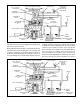
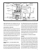
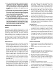
FIGURE 4 - SERVICE BRAKE APPLICATION
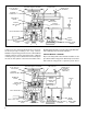
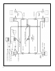
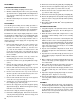
FIGURE 5 - SERVICE BRAKES HOLDING
body and cover passages to the supply of the normally closed
(NC) traction control solenoid.
Brake application air from both the rear and front axle circuits
of the brake valve enters the ATR-1DC
™
valve's primary and
secondary control ports. Secondary control pressure flexes
double check valve diaphragm “A” causing it to seal the air
passage leading to the solenoid and opening the passage
leading to double check valve “B”. Primary control air flows
to double check valve diaphragm “B”. Because primary
control pressure, from the foot valve, is 2 to 4 psi greater
than secondary control, double check valve diaphragm “B”
flexes in response to primary control and seals the air
passage leading to the secondary control. Air flows past
double check valve diaphragm “B” and through a passage in
the cover to the top of the service relay piston. In response
TRACTION CONTROL SOLENOID
SUPPLY PORT
SECONDARY
SERVICE PORT
DOUBLE
CHECK VALVE “A”
DELIVERY
PORT
EXHAUST PORT
RELAY PISTON
INLET-EXHAUST
VALVE
BLEND BACK
PISTON
SOLENOID
CONNECTOR
AIR BAG
BRAKE
CHAMBER
TONE RING
EC-16
™
OR EC-17
™
CONTROLLER
WHEEL SPEED
SENSOR
PRIMARY
SERVICE PORT
DOUBLE
CHECK VALVE
“B”
BRAKE VALVE
HELD IN
APPLIED
POSITION
BRAKE VALVE
(SHOWING
DELIVERY AIR
LINES ONLY)