
User's Manual

4
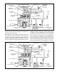
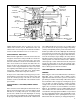
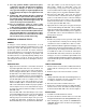
FIGURE 6 - SERVICE BRAKES RELEASING
to air pressure, the relay piston drain valve flexes and seals
the drain passage leading to the relay exhaust.
Simultaneously the relay piston moves into contact with the
exhaust portion of its inlet and exhaust valve. With the
exhaust passage sealed, continued movement of the piston
unseats the inlet portion of the inlet and exhaust valve,
allowing supply air from the reservoir to flow out the ATR-1DC
™
valve's delivery ports to the brake chambers.
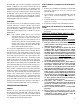
SERVICE BRAKES - HOLDING
Air pressure being delivered to the brake chambers is also
present beneath the relay piston. When air pressure above
and below the relay piston is equal, the piston moves
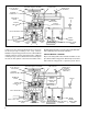
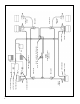
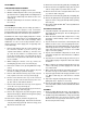
FIGURE 7 - SERVICE BRAKES - APPLYING (PRIMARY CIRCUIT DELIVERY FAILED)
TRACTION CONTROL SOLENOID
SUPPLY PORT
SECONDARY
SERVICE PORT
DOUBLE
CHECK VALVE “A”
DELIVERY
PORT
EXHAUST
PORT
RELAY PISTON
INLET-EXHAUST
VALVE
BLEND BACK
PISTON
SOLENOID
CONNECTOR
AIR BAG
BRAKE
CHAMBER
TONE RING
EC-16
™
OR EC-17
™
CONTROLLER
WHEEL SPEED
SENSOR
PRIMARY
SERVICE PORT
DOUBLE
CHECK VALVE
“B”
BRAKE VALVE
(RELEASED)
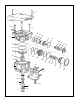
TRACTION CONTROL SOLENOID
SUPPLY PORT
SECONDARY
SERVICE PORT
DOUBLE
CHECK VALVE “A”
DELIVERY
PORT
EXHAUST PORT
RELAY PISTON
INLET-EXHAUST
VALVE
BLEND BACK
PISTON
SOLENOID
CONNECTOR
AIR BAG
BRAKE
CHAMBER
TONE RING
EC-16
™
OR EC-17
™
CONTROLLER
WHEEL SPEED
SENSOR
PRIMARY
SERVICE
CONTROL LINE
FAILURE
DOUBLE
CHECK VALVE
“B”
BRAKE VALVE
(SHOWING
DELIVERY AIR
LINES ONLY)