® ® Bendix ACom Diagnostics Diagnostic Software 6.
Contents General Information ..................................................................................................................................... 3 RP1210 Adapters......................................................................................................................................... 4 PC Hardware Requirements ........................................................................................................................ 5 Technical Assistance .......................
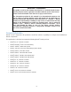
IMPORTANT – PLEASE READ This guide, as well as the software described in it, is furnished under license and may only be used or copied in accordance with the terms of the license. Please contact the Bendix Tech Team for a copy of such license. The information provided in this manual is for informational purposes only and is subject to change without notice and should not be construed as a guarantee by Bendix Commercial Vehicle Systems LLC (“Bendix”).
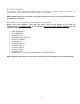
RP1210 adapters ® ® The Bendix ACom Diagnostic software relies on RP1210 compliant hardware adapters for communication. A list of the recommended adapters is shown below. NOTE: ACom Diagnostics will remain in the demo mode unless there is at least one RP1210 driver installed on the computer. What follows is a list of supported hardware adapters for the software. Before using this software, verify that the driver (.
PC hardware requirements ® ® ® Bendix ACom diagnostic software is designed to run on Windows 2000, XP, Vista and Windows 7 operating systems. Below are the minimum requirements for running the application.
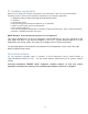
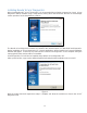
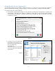
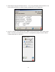
Installing Bendix ACom Diagnostics ® ® ® ® When installing Bendix ACom Diagnostics it is recommended that all other programs be closed. ACom Diagnostics will be installed using a setup wizard, during which the technician will need to acknowledge various questions for the installation to continue. Figure 1 The Bendix ACom Diagnostics software is installed to the default location of C:\Bendix\ACom Diagnostics. During installation of ACom Diagnostics 6.
Using Bendix ACom Diagnostics ® ® An icon will be placed on the desktop. Double-click the icon, or select the ACom Diagnostics application from the Bendix install directory or Program group, to launch the program. A starter screen will appear. The starter screen has various features: 1. The desired communication adapter can be selected by clicking the icon depicting a computer and tractor/trailer. (See the arrow shown on Figure 4.) Select this icon to open the driver selection screen for RP1210 adapters.
3. Alternatively the program will detect the ECU. The screen will indicate which Bendix ECU was ® ® found and the technician can select Launch to start Bendix ACom Diagnostics. Figure 5 4. Any ECU selection can be displayed in the DEMO mode by pressing the Start in Demo mode button. The Demo mode allows the technician to investigate the program’s features without communicating with an actual ECU.
® ® The following ECU controllers are supported by diagnostic software on the Bendix ACom Diagnostics 6.
Bendix ACom Diagnostics 6.5 Windows ECU Status Screen ® ® Refer to the Service Data sheet for the system being diagnosed for all cautions and warnings; certain system changes (e.g. sensor position changes) require approval from Bendix Engineering. ® ® Bendix ACom Diagnostics software opens, by default, to the Electronic Control Unit (ECU) status screen. This screen provides the technician with a snap-shot of the ECU.
Diagnostic Trouble Code (DTC) Screen The DTC screen provides the technician with active, inactive and event history information. For active DTC information, the screen is divided into three panes. The first pane displays the active DTCs; the second pane displays troubleshooting/repair information corresponding to the active DTC; and the third pane displays the connector with pin-out designations, so the technician can troubleshoot the active DTC.
Wheel Speed Sensor (WSS) Screen The Wheel Speed Sensor screen allows the technician to record the sensor output as the wheels rotate. Additionally, there is a sensor air gap field which indicates the wheel speed when the sensor starts registering speed. A lower air gap speed value (e.g. 3 to 4) indicates a properly adjusted wheel speed sensor.
Configuration Screen The Configuration screen provides the technician with the following information: ABS configuration, Load and Sensor, TRSP (if equipped), ADL, AUX I/O and Broadcast options. ABS Configuration ABS Configuration provides the technician with the number of sensors and modulators the ECU is currently configured to expect. Vehicle Data provides the technician with the vehicle type, the number of axles and the ECU orientation. Odometer displays the odometer, trip and service odometer.
Bendix Trailer Roll Stability Program (TRSP ) screen ® ® ® Note: TRSP screen will be available if the Electronic Control Unit (ECU) supports TRSP. The TRSP window allows the technician to check if TRSP is enabled, the TRSP module position, and the TRSP parameters. Figure 13 Auxiliary Design Language (ADL) The ADL screen allows the technician to verify if the ECU has an auxiliary design language program stored for a specific operation. This screen is read only.
AUX I/O The AUX I/O screen allows the technician to see how the ECU’s auxiliary inputs and outputs are configured. This screen is read only. Figure 15 Broadcast The Broadcast screen allows the technician to see which J2497 and J1939 messages are (or are not) enabled.
Pressures Screen The Pressures screen allows the technician to view and record pressures supplied by the trailer ABS system. The table below describes which pressures are reported by supported Electronic Control Units (ECUs). The pressure screen allows the technician to apply the brakes and monitor the pressures.
Bendix Trailer Roll Stability Program (TRSP ) Sensors ® ® ® NOTE: The TRSP sensors will only be available if the ECU supports TRSP. The TRSP sensors allow the technician to monitor the lateral acceleration sensor, axle load and installation angle data.
Sensor Calibration The Sensor Calibration page allows the Lateral Acceleration Sensor (LAS) to be calibrated. The trailer needs to be on a level surface for the calibration. Press “Start” to begin the calibration process, use the ® ® “Yes, No, or Cancel” choices to answer any questions. Bendix ACom Diagnostics software can be used to recalibrate the lateral acceleration sensor, clear any DTCs and display the actual sensor value.
Component Test Screen The Component Test screen allows the technician to test various components of the system such as: ® wheel speed sensors; modulators; pressure sensors; switches; and the Bendix Trailer Roll Stability ® ® Program (TRSP ) system. The Component Test screen also allows the technician to perform system tests such as: battery voltage; ABS indicator lamp; Aux I/O; and axle load.
Modulators This test allows the technician to check the modulators. The test displays the number of modulators currently configured in the ECU. To select the modulator to check, simply press the Start/Next button to start the test. Follow the instructions on the screen. The program will prompt the technician by asking “Did the modulator respond correctly?” The technician should respond by selecting the green check mark button indicating “yes”, or the red circle with a line button indicating “no.
® ® ® Bendix Trailer Roll Stability Program (TRSP ) (If Equipped) ® Note: TRSP will be available only if the Electronic Control Unit (ECU) supports TRSP . This test will allow the technician to check the TRSP sensor installation angle. To begin, the technician will need to select “installation angle”, then press the Start/Next button to begin the test. Follow the prompts to run the test.
Installation Test The Installation Test is for OEMs to make end-of-line verification tests on new vehicles. The test allows the technician to verify the proper installation of the ECU and system components. NOTE: In order for the Installation Test to run, the technician must first acknowledge the system-generated warning indicating that the vehicle must be parked on a level surface.
Customize The Customize screen allows the technician to customize some of the features in the installation test. Warning: The tests conducted must match the features of the vehicle being tested. With each vehicle, it is important to confirm that the correct set of features are being verified.
Installation Test Requirements The chart below indicates which tests are available for an Electronic Control Unit (ECU). If there is a YES next to the test name, that specific test is required in order to complete the Installation Test. If there is a “NO” shown for a test, that test is not required in order to complete the Installation Test. If there is an “N/A” shown for a test, this indicates that the ECU does not support that specific test.
ECU Information The ECU Information Test is a mandatory evaluation. It must always be run. The test provides the technician with information about how the ECU is configured.
Installation Configuration The Installation Configuration field displays a graphic – and specifics – about the expected configuration. The technician must verify that the components have been installed as shown.
Axle Load Test ® ™ The Axle Load Test is mandatory for the Bendix TABS-6 Advanced (ADV) Electronic Control Unit (ECU), ® ™ but not when inspecting the Bendix TABS-6 Multi-Voltage (MV) ECU. This test displays the detected weight on the rear axle in pounds.
Battery Voltage Test The Battery Voltage Test checks the voltage measured at the Electronic Control Unit (ECU), with the modulators de-energized, energized and de-energized. The voltage operating range is 8.0 VDC to 32.0 ® ™ VDC for Bendix TABS-6 ADV / MV and MC controllers.
ABS Indicator Lamp Test The ABS Indicator Lamp Test will illuminate and then extinguish the ABS indicator lamp while the technician verifies the correct operation of the dash-mounted ABS indicator lamp.
Installation Angle Test The Installation Angle Test displays the vertical angle of the mounted ECU. The vertical angle must be within ±5 degrees of vertical. ® NOTE: The installation angle test will only be available if the ECU supports Bendix Trailer Roll Stability ® ® Program (TRSP ).
Sensor Tests The Wheel Speed Sensor output is tested using the screen shown below.
Pressure Sensor Test The Pressure Sensor Test reads the pressures applied to the Electronic Control Unit (ECU) through the brake system. The potential number of pressure sensors supported is dependent upon the ECU.
P21/P22 Delivery Test The P21/P22 Delivery Test will check that the module is correctly plumbed to the brake chambers and test the brake delivery air pressure. Park the vehicle on level ground and chock the wheels. During this test, the delivery pressure should match the control pressure. After applying the brakes, the technician must ® ® verify that the delivery and control pressures are the same.
Scratch Pad Test The Scratch Pad Test will write information to the ECU’s scratch pad, indicating that the installation test has been performed. Once the scratch pad information is written into the ECU, the technician can select to Print or Save the installation report for their records.
Bendix ACom Diagnostics 6.5 Adaptive Cruise w/ Braking (ACB) Diagnostics ® ® ® Refer to the Bendix Service Data sheet for the system under diagnosis for all cautions and warnings; certain system changes (e.g. sensor position changes) require approval from Bendix Engineering. Launch the Bendix ACom Diagnostics software and using the starter window, select Wingman (Adaptive ® Cruise with Braking) diagnostics.
Diagnostic Trouble Code (DTC) Window - ACB Sensor The DTC screen provides the technician with active and stored DTC information. For the active and stored DTC information, the windows are two tabs; switch between the two views by clicking on the tab. Each page has two panes: the first pane displays the DTCs; and the second pane displays troubleshooting/repair information corresponding to the DTC.
Configuration Window – ACB The Configuration Window is used to display ACB sensor configuration information including the mounting offset, stationary object warning, alignment value and following distance setting configuration number. ACB Sensor Configuration Mounting Offset The ACB Sensor mounting offset provides the horizontal offset relative to the vehicle’s longitudinal axis.
Following Distance Settings The Following Distance/alerts configuration number is a numeric value that represents the current configuration of the ACB sensor following distance setting and alerts. Control Buttons for Configuration: • • • The Modify button will open change window, allowing the technician to reset the alignment value to zero and change the alert following distance configuration number. Additionally, the technician is permitted to save or load the ACB sensor configuration file.
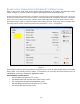
ACB Data Log ® ® ® The Wingman Data Log on the Bendix ACom Diagnostics starter window allows the technician to create an ACB data log report or clear the resettable data log file. Figure 42 Creating A Data Log Report When the technician selects Create Data Log Report, a dialogue box will open, requesting the mileage and VIN of the vehicle. Input the information and select Continue. Figure 43 Next the technician should select: Print; Print Preview; Email to Bendix; or, Save the report.
Clear Resettable Data Log When Clear Resettable Data Log is chosen, a dialogue box will open and request that the technician confirm the resettable data log file is to be cleared. Next, a dialogue box will open asking the technician if they want to save the resettable data log before clearing it. If the technician selects “Yes”, a dialogue box will open asking the technician to input the mileage and VIN.