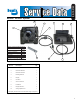
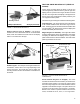
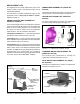
SD-19-5160 ® Bendix® XVision® System 2 5 3 1 6 7 4 XVision® System (5010086) consists of: Piece Kit/ Part Number Camera Bracket Kit 5010078 Mounting Kit (CB Mount) 5010081 Mounting Kit (Friction Hinge) 5010082 Harness Kit 5010083 Aiming Adjuster Tool * Camera/ Display Combination * * Kit/ Part is not seviceable and cannot be individually ordered through Bendix. Item No. Description 10 9 8 Qty.
NOTE: The information in this Service Data is correct and complete as of the time of printing. Options or updates to the XVision® System that were developed after publication may not be included.
SAFE MAINTENANCE PRACTICES WARNING! PLEASE READ AND FOLLOW THESE INSTRUCTIONS TO AVOID PERSONAL INJURY OR DEATH: 9. Components with stripped threads or damaged parts should be replaced rather than repaired. Do not attempt repairs requiring machining or welding unless specifically stated and approved by the vehicle and component manufacturer. When working on or around a vehicle, the following general precautions should be observed at all times. 10.
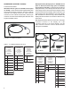
IR CAMERA BRACKET KIT (PIECE NO. 5010078) INCLUDES: Mounting Bracket Kit (piece no. 5010187) – The mounting bracket is designed to mount to the vehicle roof (horizontal mounting) or faring area (vertical mounting) and needs to be mounted parallel to the lateral axis of the vehicle (side to side). A template is provided to help guide the drilling of holes. Two stud plates with 1/4-20 studs mount the bracket to the vehicle. The final torque on the studs should be 90-100 in-lbs.
Mounting Brackets FRICTION HINGE MOUNTING KIT (PIECE NO. 5010082) Friction hinge mounting allows the driver to use the sun visor during the day and the XVision® system at night. The display pivots on a pair of friction hinges, similar to a vehicle sun visor. The hinges allow the display to be flipped out of the way of the visor and latched into either position by use of a magnet and striker plates. The friction hinge mounting kit includes the following items.
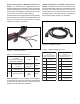
HARNESS KIT (PIECE NO. 5010083) The harness kit includes: IR Camera Harness (piece no. 5010246, service piece no. 801156) – The IR camera harness is approximately three feet long and has three connectors. The 8-pin connector connects to the display harness, the 2-pin connector connects to the IR camera window heater, and the 6-pin connector connects to the IR camera power and video. See Figure 8 and Table 1 below. Display Harnesses (CB style: piece no. 5010259, service piece no.
Vehicle Harness (piece no. 5010260, service piece no. 801157) – The vehicle harness is approximately 12 feet long and provides power to the XVision® system. The harness is made of a twisted tri-wire, which needs to be fused to the vehicle ignition and headlamps. The harness has one 3-pin connector that connects to the display harness. The vehicle harness is not designed to be mounted externally.
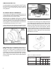
AIMING ADJUSTER TOOL The aiming adjuster tool is included with the XVision® system kit, but cannot be ordered individually. It is the only tool that should be used to install the IR camera onto the aiming adjusters. Combiner Intensity Control IR CAMERA/ DISPLAY COMBINATION The IR camera and display are serviceable and can be ordered individually. The IR camera/display combination can be purchased as an entire XVision® system. IR Camera (piece no. 5008214, service piece no.
REPLACEMENT KITS The following five kits contain replacement parts for the XVision® System. Each of the replacement kits can be ordered through Bendix. For instructions on installing replacement parts, see the appropriate section of Servicing the XVision® System, beginning on Page 10. AIMING ADJUSTER REPLACEMENT KIT (PIECE NO. 5010079) WINDOW REPLACEMENT KIT (PIECE NO. 5010192) The window replacement kit includes one replacement IR camera window, o-ring and locking pin. See Figure 16.
ELECTRICAL SYSTEM OPERATING INPUT VOLTAGE POWER AND GROUND (POWER INPUTS) The IR camera is operational in the temperature range between -40°C to 60°C. Normally, the IR camera takes about 45 seconds to warm up. However, as the external temperature gets closer to the extremes listed, the warmup time will begin to approach two minutes. Refer to Figure 19. WARNING: Vehicle power and headlight circuits MUST be fused.
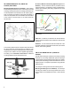
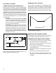
Driver’s Centerline of Sight Mounting bracket can be anywhere along driver’s centerline of sight and must be parallel to lateral axis of vehicle IR CAMERA BRACKET REPLACEMENT The new IR camera bracket will have factory-installed aiming adjusters and standoff base/pivot assembly. 1. Remove the camera shroud, if equipped. Unlock the IR camera by turning the two IR camera aiming adjusters and the IR camera standoff 1/4 turn counterclockwise using the adjuster tool. 2.
Attach the IR camera to the IR camera bracket IR CAMERA 13. Position the IR camera onto the factory-installed aiming assemblies. Refer to Figure 22. Maintaining 14. Rotate the pivot locks on the ends of the aiming assemblies 1/4 turn clockwise, using the included aiming adjuster tool. This will lock the IR camera in position. 1. Inspect the harnessing for chafing. 15. Adjust the harness, ensuring that it is not pulled tight, which could cause a water leak into the camera.
Replacing the Aiming Adjusters 1. Unlock the IR camera by turning the two IR camera aiming adjusters and the IR camera standoff 1/4 turn counterclockwise. 2. Remove the IR camera from the IR camera bracket to get easier access to the connectors. 3. Disconnect the 6-pin IR camera connector and the 2-pin window heater connector of the IR camera harness from the IR camera. Cut the cable tie to allow access. Refer to Figure 24. Cable Tie 6.
IR CAMERA WINDOW Maintaining The IR camera window, a 1.3 mm thick silicon disk, is an optical element and should be cleaned when it becomes dirty or filled with debris. Dirt and debris can affect the IR camera performance. To clean the window, use a soft, damp cloth moistened with window cleaning solution. Shop rags and paper towels will scratch optical surfaces. NOTE: The IR camera heater cannot melt large amounts of packed snow in the window area.
IR CAMERA WINDOW HEATER REPLACEMENT 1. Unlock the IR camera by turning the two IR camera aiming adjusters and the IR camera standoff 1/4 turn counterclockwise. 2. Remove the IR camera from the IR camera bracket to gain easier access to the connectors. 3. Disconnect the 6-pin IR camera connector and the 2-pin window heater connector of the IR camera harness from the IR camera. 4. Lay the IR camera face-up for easier access to the bezel retaining plug. Refer to Figure 27.
DISPLAY Maintaining the Fold Mirror Maintaining the Combiner Mirror Remove heavy dirt or grit from the fold mirror with air. Clean the fold mirror with a soft, damp cloth moistened with window cleaning solution. Shop rags and paper towels will scratch this optical surface. The combiner is a sensitive optical element and should be cleaned when it becomes dirty or filled with debris. Dirt and debris can affect the display performance. 1. Remove heavy dirt or grit with air. 2.
Display Bracket Replacement - CB Style Mount (Dashboard) Display Bracket Replacement - CB Style Mount (Overhead) 1. Unscrew and disconnect the 25-pin connector of the display harness. Refer to CB Style Mount (Dashboard) procedure. 2. Unscrew the threaded knobs from the display and brackets. Set the display, knobs, and washers aside. Exercise care to prevent dropping the washers into the venting on the dash. Display Bracket Replacement - Friction Hinge Mount (Visor) 1.
Display Replacement IMPORTANT: The display is not waterproof and should not be exposed to rain, snow, or moisture. Under extreme conditions, water may enter the circuitry through the panel buttons. In general, treat the display as you would a pocket calculator or other small non waterproof electronic instrument. IMPORTANT: The XVision ® system display technology is designed to meet severe temperature extremes.
10. From inside the cab, push the threaded nut through the hole in the roof. Cable Tie NOTE: The threaded section of the nut should protrude past the vehicle surface. Refer to Figure 31. Heat Shrinkable Shroud 6-pin connector O-Ring 2-pin connector FIGURE 32 - CONNECTING THE CAMERA HARNESSES Externally Threaded Nut ) n. ely 3 i imat x pro p (A 22. Position the IR camera onto the factory-installed aiming assemblies. Refer to Figure 33. 23.
27. Re-install the headliner and the “A” pillar cover. 28. Turn on the system to verify that it is operating correctly. 29. Aim and adjust the IR camera. Refer to Aiming the IR Camera on pages 20 and 21. TABLE 6 - VEHICLE HARNESS WIRING Vehicle Harness Connector 3 Contacts Display Harness A Vehicle ignition +12 Volts 1. Unscrew and disconnect the 25-pin connector of the display harness. B Vehicle ground 2. Remove the trim pieces covering the harness. C Headlamp active 3.
AIMING THE IR CAMERA The aiming adjusters on the IR camera bracket allow the forward field of view (FOV) of the IR camera to be adjusted horizontally and vertically. The adjustment screw head(s) will accommodate an E8 external Torx® or a T15 internal Torx®. Combiner Image When the IR camera is mounted, adjust the horizontal and vertical aiming adjusters to align the IR camera FOV with the display.
VERTICAL AIMING AND ADJUSTING The virtual image should be aligned vertically so that the horizon appears in the lower one-half to one-third of the combiner. Keeping the image at this adjustment should provide a view of the road when the vehicle is driven up and down hills. Combiner Image Horizon The vertical aiming adjusters can accommodate approximately ±4 degrees of movement. If the IR camera needs more than 4 degrees of vertical movement the IR camera bracket will need to be adjusted.
FIGURE 43 - ELECTRICAL WIRING DIAGRAM FOR XVISION® SYSTEM 23
TROUBLESHOOTING Troubleshooting Your XVision® System Situation No image on the display. Bendix logo does not appear during power-up, combiner and fold mirror are open. Possible Solutions Check that the combiner is open to an angle that allows you to see the image. Make sure the vehicle accessory power, headlights, and the XVision® system are all on. Check that the display intensity is set at an appropriate level to view the image.
Situation IR camera image is not displayed after the Bendix logo fades away on the display. Possible Solutions Wait two minutes after the XVision® system has been powered to view the IR camera image. Check to see if the IR camera window is blocked. Headlamps were turned off and the XVision® system timed out (approximately 7 seconds after the headlamps are turned off the display will turn off.) Check to see if the IR camera is aimed correctly. Display image is upside down.
NOTES 26
NOTES 27
BW2212 © 2004 Bendix Commercial Vehicle Systems LLC All rights reserved. 6/2004 Printed in U.S.A.