
Technical data


B KY 96A, KY 97A
Rev 5, Apr 2003 MM 006-05674-0005.dwd Page 5-1
SECTION V
MAINTENANCE
5.1 GENERAL INFORMATION
This section contains information on tests, alignment, inspection, cleaning, repair and
troubleshooting procedures for the KY 96A, KY 97A.
Before maintenance of the KY 96A, KY 97A is attempted, a thorough understanding
of the theory of operation (Section IV) is recommended.
5.1.1 Standard Test Signal Description
5.1.1.A. “Hard” microvolts indicates use of a 6dB pad between the signal generator
and the receiver. (Example: A receiver with 6 dB S+N/N at 2 uV hard must
have 1 uV of sensitivity).
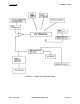
5.1.1.B. A standard modulator test signal is a 0.4 Vrms, 1 kHz tone, open circuit, with
the network shown in Figure 5-3.
5.1.1.C. A standard audio test signal is an RF carrier amplitude modulated 30% at
1,000 +/- 100 Hz.
5.2 TEST EQUIPMENT
5.2.1 REQUIRED TEST EQUIPMENT
The following test equipment, or equivalent, is required to properly align and test the
KY 96A, KY 97A. All test equipment must be calibrated before attempting alignment.
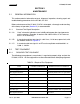
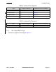
TABLE 5-1 Required Test Equipment
TYPE CHARACTERISTICS REPRESENTATIVE MODELS
Power Supply 27.5 V @ 6 amps Sorensen SRL 40-6 or equivalent.
RF Signal Generator Boonton Model 211A or equivalent
Audio Signal Generator HP 200CD
Digital Multimeter Fluke 8000A
RF Wattmeter Bird Model 611
Frequency Counter HP 5245L
Audio Wattmeter with Load Eico Model 261
Oscilloscope Tektronix Model 454 or equivalent
RF Signal Generator HP 606A