
Technical data


B KY 96A, KY 97A
Rev 5, Apr 2003 MM 006-05674-0005.dwd Page 5-6
is referenced to 1 kHz, compressor enabled. (This is an optional test that re-
quires a distortion analyzer).
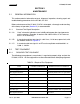
5.3.2.F. Audio Response:
350 Hz = ___NMT 6dB down 1 kHz = ___ 0dB 2.5 kHz = ___NMT 6dB down
Input a 100 uV standard audio test signal into the unit. Disable the audio com-
pressor by grounding pin 10 on P96A1, P97A1. Monitor the receiver output.
5.3.2.G. Compressor: ______NMT +/- 3 dB
Input a 100 uV standard audio test signal into the unit. Vary the modulation
from 30% to 85%.
5.3.2.H. Squelch:
NOTE: Squelch adjustments must be performed in the following order:
5.3.2.H.1 Set the unit to 126.975 MHz.
5.3.2.H.2 Carrier/Noise Squelch set to open at 2 uV (+1 uV, -0.5 uV) and close at NMT
4 dB below the squelch opening.
5.3.2.H.3 Carrier/Noise Squelch _____OK.
5.3.2.H.4 With unit set to 126.975 MHz, input an 8 kHz 85% modulated signal into the
unit. Set the carrier squelch to open at +/- 12.5 uV.
5.3.2.H.5 Carrier Squelch _____OK.
5.3.2.H.6 Intercom: ______ NLT 100 mW into 500 ohm.
Input a 100 mV 1 kHz signal into Mic Intercom, pin K of P96A1, P97A1.
5.3.3 Transmitter
5.3.3.A. RF Power Output:
Connect a wattmeter to the antenna output and record the following unmodu-
lated values.
Set A + input to ______ 13.75 Vdc @ pin 11______
27.5 Vdc @ pin 12 ______
118.00 MHz ______ 5.0 watts Min. 13.75 V units
______ 5.0 watts Min. 27.5 V units
126.97 MHz ______ 5.0 watts Min. 13.75 V units
______ 5.0 watts Min. 27.5 V units
135.97 MHz ______ 5.0 watts Min. 13.75 V units
______ 5.0 watts Min. 27.5 V units