
Technical data


B KY 96A, KY 97A
Rev 5, Apr 2003 MM 006-05674-0005.dwd Page 5-10
5.4.3 VCO Adjust
Set frequency to 135.975 MHz and put unit in transmit mode.
Adjust the Tx frequency to 135.975 MHz using C134. This should be done with-
in 60 seconds of turn on.
Put unit in receive mode. Read voltage at TP102 and adjust T105 for 7.1 volts.
5.4.4 Viewing Angle Adjust
The viewing angle adjust is accessible through an opening on the left side of
the unit front panel. The viewing angle adjust is operator adjustable, and is to
be set for optimum display viewing angle by the operator. No alignment is nec-
essary for unit maintenance or repair.
5.4.5 Transmitter
5.4.5.1 Power Set
Adjust R256 to obtain minimum rated power across the band, unmodulated.
Adjust C418 for minimum power variation across the band.
KY 96A 5 watts
KY 97A 5 watts
5.4.5.2 Modulator Adjust
Set the frequency selector to 128.50 MHz. Apply a 0.4 volt 1 kHz standard test
signal to the microphone input and key the transmitter.
Observe the demodulated RF output from the linear detector on an oscilloscope
and adjust R1009 for 85% modulation.
Adjust R267 for 70% modulation. Check 118.00 MHz and 135.975 MHz and
re-adjust only if the modulation is lower than 70%.
5.4.5.3 Sidetone Adjust
Apply a 0.4 volt 1 kHz standard test signal to the microphone input and key the
transmitter. Adjust R221 for 4 mW of audio into a 500 ohm load.
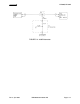
5.4.6 Receiver Alignment
5.4.6.1 RF/IF Alignment
The following alignment is to be made at 128.50 MHz. Connect the unit to the
RF signal generator through a 6 dB pad. Turn unit on with squelch and com-
pressor disabled and apply sufficient RF signal for approximately 4.75 volts dc
at TP105.
Load and tune L101, L103, L105 and L107 using a 220 ohm resistor from the
top of each tank to ground in the following sequence.
Load L103 tune L101
Load L101 tune L103