IMPORTANT SAFETY INSTRUCTIONS SAVE THESE INSTRUCTIONS EUROPEAN USERS 400V 50Hz SUPPLY DETAILS ARE INCLUDED WITH ELECTRICAL CONTROL BOX. DISREGARD SUPPLY WIRING DETAILS IN THIS MANUAL PLEASE READ THE ENTIRE CONTENTS OF THIS MANUAL PRIOR TO INSTALLATION AND OPERATION. BY PROCEEDING YOU AGREE THAT YOU FULLY UNDERSTAND AND COMPREHEND THE FULL CONTENTS OF THIS MANUAL. FORWARD THIS MANUAL TO ALL OPERATORS. FAILURE TO OPERATE THIS EQUIPMENT AS DIRECTED MAY CAUSE INJURY OR DEATH.
9,000 POUND CAPACITY, COMMERCIAL GRADE FOUR POST AUTO / TRUCK LIFT This instruction manual has been prepared especially for you. Your new lift is the product of over 40 years of continuous research, testing and development; it is the most technically advanced lift on the market today. READ THIS ENTIRE MANUAL BEFORE INSTALLATION & OPERATION BEGINS. RECORD HERE THE LIFT AND POWER UNIT INFORMATION WHICH IS LOCATED ON THE SERIAL NUMBER DATA PLATES ON THE LIFT AND ON THE POWER UNIT Santa Paula, CA USA www.
IMPORTANT NOTICE OWNER’S RESPONSIBILITY To maintain the lift and user safety, the responsibility of the owner is to read and follow these instructions: Do not attempt to install this lift if you have never been trained on basic automotive lift installation procedures. Never attempt to lift components without proper lifting tools such as forklift or cranes. Stay clear of any moving parts that can fall and cause injury.
TABLE OF CONTENTS Warranty / Serial Number Information . . . . . . . . . . . . . . . . . . . . . . . . . . . . . . . . . . . . . . . . . . . . . . . . . . . . 2 Definitions of Hazard Levels . . . . . . . . . . . . . . . . . . . . . . . . . . . . . . . . . . . . . . . . . . . . . . . . . . . . . . . . . . . 3 Owner’s Responsibility . . . . . . . . . . . . . . . . . . . . . . . . . . . . . . . . . . . . . . . . . . . . . . . . . . . . . . . . . . . . . . . . . 3 Before You Begin . . . . . . . . . . . . . . .
INSTALLER / OPERATOR PLEASE READ AND FULLY UNDERSTAND. BY PROCEEDING YOU AGREE TO THE FOLLOWING: Failure to follow danger, warning, and caution instructions may lead to serious personal injury or death to operator or bystander or damage to property. t I have visually inspected the site where the lift is to be installed and verified the concrete to be in good condition and free of cracks or other defects.
INTRODUCTION 1. Carefully remove the crating and packing materials. CAUTION! Be careful when cutting steel banding material as items may become loose and fall causing personal harm or injury. 2. Check the voltage, phase and proper amperage requirements for the motor shown on the motor plate. Wiring should be performed by a certified electrician only.
t t t t t t t Rotary Hammer Drill or Similar 3/4” Masonry Bit Hammer 4 Foot Level Open-End Wrench Set: SAE /Metric Socket And Ratchet Set: SAE/ Metric Hex-Key / Allen Wrench Set TOOLS REQUIRED t t t t t t t Medium Crescent & Pipe Wrenches Torque Wrench Crow Bar Chalk Line Medium Flat Screwdriver Tape Measure: 25 Foot Minimum Needle Nose Pliers An air supply (75-90PSI Min / 5 CFM Min.) will be required for the safety-lock mechanisms. See Step 11.
When removing the lift from shipping angles pay close attention as the posts can slide and can cause injury. Prior to removing the bolts make sure the posts are held securely by a fork lift or some other heavy lifting device.
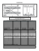
FLOOR PLAN B Note: Power Unit can be located at either “X” location. H X K A Diagonal Measurements Must Be Equal* G J F E I X C *IMPORTANT NOTE* Check Diagonal Measurements To Ensure Square Layout Diagonal Measurements Must Be Equal. HD-9ST HD-9STX Lifting Capacity MODEL 9,000 lbs / 4082 Kg. 9,000 lbs / 4082 Kg. Max capacity / front axle 4,500 lbs. / 2,041 kg 4,500 lbs. / 2,041 kg Max capacity / rear axle 4,500 lbs. / 2,041 kg 4,500 lbs.
FLOOR PLAN B Note: Power Unit can be located at either “X” location. H X K A Diagonal Measurements Must Be Equal* G J E I X D F C *IMPORTANT NOTE* Check Diagonal Measurements To Ensure Square Layout Diagonal Measurements Must Be Equal. MODEL HD-9 HD-9XW HD-9XL Lifting Capacity 9,000 lbs. / 4082 Kg. 9,000 lbs. / 4082 Kg. 9,000 lbs. / 4082 Kg. Max capacity / front axle 4,500 lbs. / 2,041 kg 4,500 lbs. / 2,041 kg 4,500 lbs. / 2,041 kg Max capacity / rear axle 4,500 lbs.
CLEARANCES HD LIGHT DUTY APPROACH B. Place target on floor at column positions (NOT on column base plates) and record readings. 1. Lift Location: Use architects plan and Engineers automatic level (transit) when available to locate lift. The above shows clearances of a typical bay layout. Lift floor area should be level. C. Find the highest of the four locations. Find the difference between the readings at each of the remaining three columns and the highest reading. 2.
POWER UNIT LOCATION IMPORTANT NOTE The Power Unit can be located at either “X” location shown below. It is important to locate the POWERSIDE Runway (with Cylinder) on the SAME SIDE as the power unit location. Utility rails on the side of each Runway MUST be installed to the inside. For the remainder of this instruction we will illustrate the Power Unit mounted at the DRIVER-SIDE (LEFT) FRONT Column - TOP ILLUSTRATION.
STEP 3 (Column & Crosstube Installation) 1. Place a chalk line on the floor according to the floor plan layout. Pay attention to the power Unit location. Locate and stand the columns at their respective locations. DO NOT BOLT Columns down at this time. Use caution to prevent the Columns from falling over. (See Fig. 3.1) Fig 3.3 Fig 3.1 (If not bolting lift to the floor, skip to Item 3.) 2. To estimate the shim requirements, place a target on floor at each Column position and record the readings.
5. The Columns and Crosstubes will now be in position and spaced properly for the Runways. 2. Manually raise the Crosstubes until the Primary Safety Locks engage and rest on the third or fourth lock position or approximately 24” off the ground. (See Fig 4.1) 6. Thread the jam nut all the way to the Ladder. Install the column TOP CAPS using the M16 x 2 Hex Bolts, nuts & washers. Turn the Top Nut on each Safety Ladder until the jam nut is touching the Ladder and the TOP CAP.
STEP 5 Fig 5.4 (Powerside Runway Installation) 1. Locate the Powerside Runway easily identified by the Cylinder and Sheave roller mounting structures welded on the underside. The Powerside Runway will be positioned on the side of the lift where the power unit is installed. (See Fig. 5.1) Fig 5.1 Powerside Runway Offside Runway STEP 6 2. Install Cylinder and Cable Block as shown. (See Fig. 5.2-5.3) (Offside Runway Installation) Fig 5.2 1.
D C HD-9XL HD-9XL A B HD-9XL D HD-9XW HD-9XL C D HD-9STX HD-9XW C HD-9STX A B HD-9STX B A HD-9XW 5595915 D HD-9ST HD-9STX HD-9XW 5595910 C 5595399 5595472 5595397 5595471 5595919 5595479 5595909 5595478 5595918 5595912 5595908 5595902 5595905 5595900 5595916 HD-9ST D HD-9 5595457 5595906 A C HD-9 B B HD-9 5595474 Part Number HD-9ST A HD-9ST Cable Lift HD-9 Description CABLE ASSEMBLY Ø10 x 9932mm CABLE ASSEMBLY Ø10 x 8332mm CABLE ASSEMBLY Ø10 x
STEP 7 (Cable / Sheave Installation) 1. Inspect Cables to ensure proper lengths. All Cables should have ID tags showing proper Cable lengths. Failure to route Lifting Cables as described may lead to serious personal injury and/or death to operator or bystander and/or may cause damage to property. 2. In order to install the Cables it is necessary to first extend the Hydraulic Cylinder. Remove both Cylinder port plugs then use an air gun or come-along to extend the Cylinder.
STEP 9 Fig 8.3 (Power Unit Installation) 1. Mount the Power Unit to the Mounting Bracket using the M8 Hex Head Bolts and Nylock Nuts then fill the reservoir with 12 quarts of 10-WT hydraulic oil or Dexron III automatic transmission fluid. (See Fig. 9.1) Flat Washers 4. Tighten each Nut until there is at least 2-3 threads protruding through the top of the nut. The Cables will remain loose until start up and final Cable adjustments are made. (See Fig. 8.
The standard Power Unit for your lift is 220 volt, 60HZ, single phase. All wiring must be performed by a certified electrician only. SEE WIRING INSTRUCTIONS AFFIXED TO MOTOR FOR PROPER WIRING INSTRUCTIONS. DO NOT run Power Unit with no oil. Damage to pump can occur. The Power Unit must be kept dry. Damage to Power Unit caused by water or other liquids such as detergents, acid etc., is not covered under warranty. Operate lift only between temperatures of 41 °- 104° F.
Fig 10.5 90° Air Line Compression Fitting 90° Air Line Compression Fitting 90° O-Ring Fitting 5. Route both the Power Unit Hydraulic Hose and TWO (2) lengths of Air Line through the Flex Hose. (See Fig. 10.6) Fig 10.6 2. Remove the captive nut on the Compression Fitting. Insert the Plastic Air line through the alignment sleeve and into the end of the fitting until it bottoms out. Then tighten the nut on the fitting. (See Fig 10.3) Air Line Hose Flex Hose Power Hose 90° Hose End Fig. 10.3 6.
STEP 11 7. Connect the hydraulic hose and air line as shown below making sure the hydraulic hose passes through the retaining rings. MAKE SURE HOSES ARE KEPT CLEAR OF CABLES. There will be one air line hose left unconnected in this step. This air line will be used to activate the pneumatic safety locks in the next step. See pages 19 & 20 for Compression Fitting instructions. (See Fig. 10.8) Straight Hose End ( Routing Air Lines) 1.
SAFETY AIR LINE ROUTING NOTE: CUT THE PROVIDED 1/4” AIR LINE TUBING WITH A SHARP BLADE TO LENGTHS AS REQUIRED. TUBING MUST BE CUT SQUARE WITH ALL PLASTIC BURRS REMOVED. AIR TUBING ASSEMBLY: SEE PAGE 19 FOR ASSEMBLY OF AIR LINE TUBING INTO FITTING. CAUTION: REMOVING THE AIR TUBING FROM THE COMPRESSION FITTINGS WILL CAUSE DAMAGE TO THE TUBING ITSELF. USE OF A DAMAGED AIR LINE MAY RESULT IN SAFETY LOCK FAILURE.
DO NOT PERFORM ANY MAINTENANCE OR INSTALLATION OF ANY COMPONENTS WITHOUT FIRST ENSURING THAT ELECTRICAL POWER HAS BEEN DISCONNECTED AT THE SOURCE OR PANEL AND CANNOT BE RE-ENERGIZED UNTIL ALL MAINTENANCE AND/OR INSTALLATION PROCEDURES ARE COMPLETED. IMPORTANT POWER-UNIT INSTALLATION NOTES n DO NOT run power unit with no oil. Damage to pump can occur. n The power unit must be kept dry. Damage to power unit caused by water or other liquids such as detergents, acid etc., is not covered under warranty.
STEP 12 STEP 13 (Power Unit Hook Up) (Inspecting The Slack Safety Springs) 1. Have a certified electrician run the power supply to motor. Refer to the data plate found on the motor for proper power supply and wire size. The following steps involve the SLACK CABLE SAFETY DEVICE and MAIN SAFETY. Failure to follow these steps could result in serious injury or death in the event of cable failure. RISK OF EXPLOSION! 1. Inspect the ends of ALL SAFETY LOCK SPRINGS as shown.
5. Check to make sure that all Slack Safety Locks are cleared and free. (See Fig. 14.1) KEEP HANDS AND FEET CLEAR. Remove hands and feet from any moving parts. Keep feet clear of lift when lowering. Avoid pinch points. 9. Check all MAIN SAFETY LOCKS to make sure they move freely and spring back to the lock position when released. Lubricate all SAFETY PIVOT points with WD-40 or equal. 10.
STEP 16 (Attaching the Approach Ramp /Tire Stops) 1. Install the Front Tire Stops at the forward side of the lift. Slide the Tire Stop Pin through the Ramp and the Tire Stop and secure with Rotor Clips. (See Fig. 16.1) ALWAYS WEAR SAFETY GOGGLES 4. Assemble the Washers and Nuts on the anchors then tap each hole with a hammer until the washer rests against base plate. Be sure that if shimming is required, enough threads are left exposed. (See Fig. 15.3) Fig 15.3 Fig 16.1 2.
STEP 17 Fig 17.2 (Leveling / Synchronizing) 1. Using an engineer’s automatic Level (transit), locate the Level, at a convenient location in the shop that allows an unobstructed view of all four corners of the runways. Fig 17.1 11. Next, load vehicle onto the lift. 12. Raise the lift to full height. Listen and watch as the primary safeties engage the safety ladder. Synchronize by adjusting the cables so that all four latches click at same time.
OPTIONAL EQUIPMENT INSTALLATION Rolling Jack maximum weight capacity for use with HD-9 is 4,500 lb (2,041 kg) per unit.
Adapter Plate Required for HD-9,12,14; HDS-14 Adapter Plate Required for HD-9,12,14; HDS-14 30
POST-INSTALLATION CHECK-OFF records recommended by the manufacturer or ANSI/ALI ALOIM-2000, American National Standard for Automotive Lifts-Safety Requirements for Operation, Inspection and Maintenance.
3. Before raising vehicle, be sure all personnel are clear of the lift and surrounding area. Pay careful attention to overhead clearances. lift service personnel and genuine BendPak parts to make repairs. • THOROUGHLY train all employees in use and care of lift, using manufacturer’s instructions and “Lifting It Right” and “Safety Tips” supplied with the lift. 4. Raise the lift to the desired height by pressing the push button on the power unit. 5.
WEEKLY MAINTENANCE 1. Lubricate all Sheave and rollers with general purpose oil. 2. Check all Cable connections, bolts and pins to ensure proper mounting. WHEN LOWERING THE LIFT PAY CAREFUL ATTENTION THAT ALL PERSONNEL AND OBJECTS ARE KEPT CLEAR. ALWAYS KEEP A VISUAL LINE OF SIGHT ON THE LIFT AT ALL TIMES. ALWAYS MAKE SURE THAT ALL LOCKS ARE DISENGAGED. IF ONE OF THE LOCKS INADVERTENTLY LOCKS UPON DESCENT THE VEHICLE MAY DISMOUNT CAUSING PERSONAL INJURY OR DEATH. 3.
WIRE ROPE INSPECTION AND MAINTENANCE t Lifting cables should be replaced every three - five years or when visible signs of damage are apparent. DO NOT USE LIFT WITH DEFECTIVE / WORN CABLES. t Lifting cables should be maintained in a well-lubricated condition at all times. Wire rope is only fully protected when each wire strand is lubricated both internal and external. Excessive wear will shorten the life of the wire rope.
Safe Lift Operation Automotive and truck lifts are critical to the operation and profitability of your business. The safe use of this and other lifts in your shop is critical in preventing employee injuries and damage to customer’s vehicles. By operating lifts safely you can ensure that your shop is profitable, productive and safe. Safe operation of automotive lifts requires that only trained employees should be allowed to use the lift.
t DO NOT leave the controls while the lift is still in motion. t DO NOT stand directly in front of the vehicle or in the bay when vehicle is being loaded or driven into position. t DO NOT Go near vehicle or attempt to work on the vehicle when being raised or lowered. t REMAIN CLEAR of lift when raising or lowering vehicle. t DO NOT rock the vehicle while on the lift or remove any heavy component from vehicle that may cause excessive weight shift.
LIFT WILL NOT RAISE POSSIBLE CAUSE 1. Air in oil, (1,2,8,13) 2. Cylinder binding, (9) 3. Cylinder leaks internally, (9) 4. Motor run backward under pressure, (11) 5. Lowering valve leaks, (3,4,6,10,11) 6. Motor runs backwards, (7,14,11) 7. Pump damaged, (10,11) 8. Pump won’t prime, (1,8,13,14,3,12,10,11) 9. Relief valve leaks, (10,11) 10. Voltage to motor incorrect, (7,14,11) REMEDY INSTRUCTION 1. Check for proper oil level. . . . . . . . . . . . . . . . . . . . . . . . . . .
MOTOR WILL NOT RUN POSSIBLE CAUSE 1. Fuse blown, (5,2,1,3,4) 2. Limit switch burned out, (1,2,3,4) 3. Microswitch burned out, (1,2,3,4) 4. Motor burned out, (1,2,3,4,6) 5. Voltage to motor incorrect, (2,1,8) REMEDY INSTRUCTION 1. Check for correct voltage . . . . . . . . . . . . . . . . . . . . . . . . . . Compare supply voltage with voltage on motor name tag. Check that the wire is sized correctly. N.E.C. table 310-12 requires AWG 10 for 25 Amps. 2. Check motor is wired correctly . . . .
WILL NOT RAISE LOADED LIFT POSSIBLE CAUSE 1. Air in oil, (1,2,3,4) 2. Cylinder binding, (5) 3. Cylinder leaks internally, (5) 4. Lift overloaded, (6,5) 5. Lowering valve leaks, (7,8,1,5,9) 6. Motor runs backwards, (10,12,9) 7. Pump damaged, (5,9) 8. Pump won’t prime, (1,2,3,4,5,11,9) 9. Relief valve leaks, (8,5,9) 10. Voltage to motor incorrect, (10,12,5) REMEDY INSTRUCTION 1. Check oil level . . . . . . . . . . . . . . . . . . . . . . . . . . . . . . . . . .
LIFT WILL NOT STAY UP POSSIBLE CAUSE 1. Air in oil, (1,2,3) 2. Check valve leaks, (6) 3. Cylinders leak internally, (7) 4. Lowering valve leaks, (4,5,1,7,6) 5. Leaking fittings, (8) REMEDY INSTRUCTION 1. Check oil level . . . . . . . . . . . . . . . . . . . . . . . . . . . . . . . . . . . The oil level should be up to the dip stick in the reservoir with the lift all the way down. 2. Oil seal damaged and cocked . . . . . . . . . . . . . . . . . . . . . . . . Replace oil seal around pump shaft. 3.
Grease Port / Lubrication Locations Lubricate Once A Week Torque Recommendations VALUES ARE STATED IN FOOT POUNDS (ft-lb) SAE 0-1-2 SAE Grade 5 SAE Grade 8 SOCKET HEAD CAP SCREW CLASS 4.8 CLASS 8.8 CLASS 10.9 CLASS 12.9 Bolt Size (SAE) Bolt Size (Metric) 1/4-20 M6 x 1.0 6 10 14 13 5/16-18 M8 x 1.25 12 19 29 31.4 3/8-16 M10 x 1.50 62 7/16-14 20 33 47 32 54 78 1/2-13 M12 x 1.75 47 78 119 108 9/16-12 M14 x 2.00 69 114 169 173 5/8-11 M16 x 2.
MAINTENANCE RECORDS ____________________________________________________________________ ____________________________________________________________________ ____________________________________________________________________ ____________________________________________________________________ ____________________________________________________________________ ____________________________________________________________________ ____________________________________________________________________ _________